The ‘Sidereal’ Clock

Note: This post is based on a word document I wrote and archived back when I finished this project in April of 2014.

Background

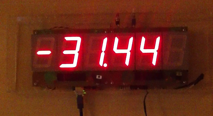
The Sidereal Clock is a simple thing. It tells you exactly how much daylight you have left. Once the sun sets, it goes negative and tells you how much nighttime remains. I realize it’s a misnomer, ‘sidereal time’ (http://en.wikipedia.org/wiki/Sidereal_time) would really describe a clock based around the movement of the fixed stars, but ‘daylight clock’ is a rather ambiguous and forgettable name.

The Sidereal Clock started from an idea. Well, someone else’s idea. My academic advisor saw a clock at an art installation (supposedly by James Campbell – http://www.jimcampbell.tv/portfolio/objects/untitled_for_the_sun/, although I haven’t seen it with my own eyes) that measured the percent of daylight remaining using a photo detector to determine when the last sunrise and sunset were. My advisor thought this was a really novel way of showing time, and I agreed. The implementation, however elegant, is rather impractical. It requires some reliable uninterrupted access to outdoor light, which suggests a ruggedized installation of a photo detector outdoors with a line leading inside to the display unit. Certainly impractical for many people, but really cool nonetheless.

Generation 1: Wired

My advisor, had an upcoming freshman class and some old 2.4” seven segment displays scrapped from a bowling alley.  He’d suggested a clock that would provide the same information, but which would show his freshman the cool stuff you could do with an Arduino. This meant the following requirements:

Figure 1: Wired Clock
  1. Automatic network time setting.
  2. Those bright displays, each with three 2.4” digits.
  3. A way to calculate sunrise and sunset.

What I came up with wasn’t much of a leap. I basically ganged together the displays, which were on boards with handy shift registers, grabbed and Ethernet Shield, and off I went!

I could of course get the time from NTP servers (there’s even an example that comes with the Ethernet Shield), and I found that the Navy offers a web page that would calculate the Sunrise and Sunset time for me. It’s actually pretty neat! All I had to do was scrape it for that data (check it out http://aa.usno.navy.mil/cgi-bin/aa_pap.pl). I wrote a tiny PHP script which I hosted on my own domain to act as an intermediary and then had my Arduino parse the text output and use it to set my clock. Bam!

I laser cut a relatively crude acrylic case in our campus shop and brought it to show the students. Overall, a decent outcome for a few evenings work, if I do say so myself.

Generation 2: Wireless

Unfortunately, my advisor didn’t particularly like the fact that it required an Ethernet cable (neither did I, to be honest), but I let it sit for a season, because it was providing good service on his wall and occasionally inspiring students. After about six months, the glue holding the front of the hastily assembled acrylic case gave out. I decided to use that as an excuse to improve the design. I managed to get a hold of the then brand new Adafruit CC3000 breakout (https://www.adafruit.com/products/1469) and see if it would do the trick for NTP. It worked like a charm (that CC3000 chip is really cool in my opinion, although I must disclaim having been a TI intern in the past – but not involved with the CC3000). The next trick was to free myself from web page parsing. After some more web spelunking, I found someone who had solved exactly this problem in C, and all that was required was to port it to my Arduino sketch. That original code can be found here (http://souptonuts.sourceforge.net/code/sunrise.c.html).

Figure 2: Wireless Clock Guts

Finally, I added a real time clock module based on the DS1307, which allowed me to virtually never synchronize with the internet. At this point, I modified the firmware so that it would only check NTP when the user

Figure 3: Wireless Clock

pressed a button on the top of the clock. The downside to all this was that the addition of the CC3000 libraries, combined with the DS1307, various time libraries, and lots of text in the serial interface used for setting parameters (like GPS coordinates) meant that there simply wasn’t enough program memory (EEPROM) on the 32k of an Arduino Uno, and I had to switch to a Mega2560. Still, all in all, a successful result, even if it is rather ugly on the inside.

I dutifully returned my Wi-Fi friendly clock to my advisor and it found a home on his wall, once again occasionally coming down to show students just how much cool stuff you could pack onto a measly Arduino.

Generation 3: Single Board

Thinking I was done with the project I nearly moved on, but the cool factor of the design kept bugging me. I wanted one for my own wall. After some searching, I actually found that Jameco (our beloved local bay-area parts supplier) carried the exact same, beautiful 2.4” tall seven segment LEDs (http://www.jameco.com/webapp/wcs/stores/servlet/Product_10001_10001_97199_-1) this opened the possibility of building a single board version of the clock. I started down the road of a full replication of my previous effort, including an integrated Mega2560, CC3000 and RTC. After getting said board half laid out, I came to a realization…wireless is a luxury, and I have no need for it in a design for me. Stripping out the wireless removed a lot of fat from the code. I could pull most of the serial interface as I didn’t need to set things like SSID and password, I could pull several large libraries, etc. It made it trivial to fall back to an Atmega328P (of Arduino Uno fame) as opposed to the more complex and expensive surface mount microcontroller used in the Mega2560.

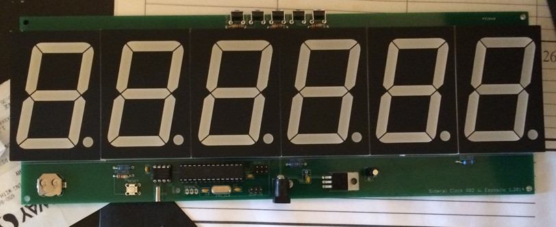
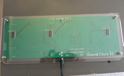
The final result consisted of 6 LED Digits, three  TLC5925I’s (LED driver ICs), five buttons for input, a regulator, a DS1307 with a watch battery, an atmega328P and a handful of resistors and capacitors.

I pretty quickly stripped down the board to a much smaller (and less costly) bill of materials and produced a final version, containing an Atmega, with ICSP, a Real Time Clock, and LED drivers. Everything was easy, or so I thought. It turned out that I had foolishly rounded down in my measurement of the LED’s width when creating a footprint for Eagle CAD.  Unfortunately, this meant that while I could squeeze the LEDs into their footprint, the rounding errors added up across all six LEDs to a 0.1” overhang. Of course, this stress meant that the entire board ended up curved! It worked, but that’s not okay.

Figure 4: Bent Board

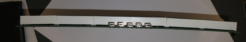
A quick fix revision (and $50 and several weeks of waiting) later and all was well!

Figure 5: Fixed board.

The Enclosure

Finally, the design needed a better enclosure.

Figure 6: Side View Of Enclosure

I’m going out of order here because I came up with this design as I laid out the board, but it fits better as its own section. As I mentioned, I had originally built an acrylic enclosure in the campus shop, designing the entire apparatus to hang from the back plate using either double stick tape or standoffs. This was a haphazard arrangement, and designing my own board opened up an opportunity to simplify things.

Figure 7: Back Of Enclosure

I discovered Ponoko (ponoko.com), which will laser cut from an SVG and mail directly to your door. Given that I had spent most of a day in the shop simply waiting for an opportunity to use the laser cutter (behind a long line of students who had never used it before and had come essentially unprepared to cut anything), I decided to give them a try. Despite the fact that they are listed as a New Zealand company, it turns out that their Acrylic shipped from a shop east of the San Francisco Bay, meaning that I would get my parts 24 hours after they shipped, even with the cheapest

Figure 8: Contrast issues without a diffuser

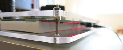
shipping rates. Combine that with the $50 annual fee to use the campus shop and the long delay, I decided to give them a try. I got a discounted rate and my first piece ended up being on the order of $20, which was stunning. I ended up cutting two pieces of acrylic and using #4 screws to create a PCB sandwich, with a hanging hole in the back of the clock.

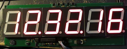
Unfortunately, there was a downside to clear

Figure 7: Paper Diffuser

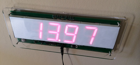
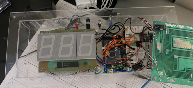
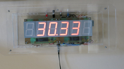
acrylic. Unlike the first LEDs, the new LEDs from Jameco have a black background (this is visible in the picture of the assembled board, to the right). This means that even the unlit LED segments have a fairly high contrast with their background. That lack of contrast makes the clock extremely difficult to read despite the display being absolutely huge. The first obvious solution was to use some thin paper as a diffuser, which works reasonably well, but it’s still not particularly pretty.

Figure 8: Finished Design

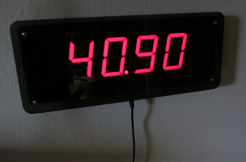
I decided to place a second order from Ponoko, of the same design, but in smoked gray acrylic. This design, diffuser omitted, came back absolutely beautiful and represents a nearly final design. The one last tiny change came from the realization that I could fit three clock enclosures on two sheets of acrylic if I shrank the height of the face by 0.1”.

The final BOM in quantity one is a little over $100, mostly due to the PCB, LEDs, and Acrylic, although I suspect in large quantities, it would be reduced to less than half that.

All in all, I’m really happy with how the entire clock came out and who knows, maybe at some point I’ll make a kit out of it or something, but for now, I intend to pass them out to friends and family as the occasional unique gift.

The Best Desoldering Iron (for under $50)


There is an eternal debate among those of us who wield the iron, as to what the best way to go about desoldering components is. For surface mount components, I’d dare to say it’s a mostly settled question (I tread here at my own peril) with hot air rework stations being excellent and reasonably functional low cost units from china being widely available. I myself have one of these, which works reasonably well.

Figure 1: Sparkfun hot air rework station.

But when it comes to through hole components, the debate is much more raucous. Many people swear by application of their main iron and plain old solder wick. This was the first way to remove a soldered component that I was personally introduced to, and still find it a valuable tool in my kit.

Figure 2: Solder wick.

Others use so called “solder suckers” – either of the spring or bulb type.

Figure 3: Spring type solder sucker.

Figure 4: Bulb type solder sucker.

Personally, I’ve tried to use these on and off for years in a pinch in other people’s labs, and I have found them worse than garbage. I’ve never once successfully removed a component using one, but the heat I had to apply to try and keep the solder molten long enough to move the sucker in place has ruined many parts and pads under my watch. Never mind the awkwardness of tying to wrangle the component, sucker, and iron all at the same time.


I still remember the first time I was introduced to the “professional” solution to this problem. I was an undergraduate and I had soldered down some 16 pin dip that needed to be removed. The TA suggested I go ask the lab technician for use of his desoldering station, which was a concept I had not, to that point, considered.

Figure 5: Professional Weller desoldering station.

I still remember the sense of awe I had when I touched the iron to a pin, tapped a button, and the pin was clean. Voila!

Since then, I have been lucky enough to usually have access to them when I need them in professional environments, and I still aspire to own one someday – some day that I find one dirt cheap as surplus. But until then, I’ve found a pretty good alternative.

About ten years ago at Radio Shack, I found a bulb type desoldering iron, for about $17. I picked it up, skeptical, and brought it home. The next time I needed to remove a component, I plugged in this scraggly little iron. No temperature control and a rubber bulb. I was sure it would be garbage.

Figure 6: Bulb type desoldering iron.

But no, almost as easily as the professional irons, the bulb type iron took two passes to remove all the solder from a pin, but it worked. And more importantly, it worked without lifting a pad or driving a component to thermal death.

Figure 7: Vacuum tip.

Since then, it has been my go-to home solution for desoldering, and honestly, I’ve felt no severe need to shell out the cash for a professional Weller desoldering station.

In ten years since I got it, the price seems to have gone up by $6, but what appears to be the identical iron is still available at amazon (don’t worry, it’s not a referral link). Who knows, maybe the odd, still open Radio Shack even stocks them.

The “Final” VU-Meter schematic

After all that work, I found that the lower “inerita” of the correctly connected tubes meant that the display itself had a twitchy response — the fix was simple, increase the capacitance at the VU-Meter node. I simply replaced the 0.1uF ceramic caps at the peak detector stage with 1uF electrolytic. Since this is a single rail design, that shouldn’t be a problem.

Additionally, since the tubes need 5mA instead of 10+ to go full scale, I replaced the 220Ω control current limiting resistors with 1kΩ resistors — the trim pots now sit most of the way to 0Ω instead of most of the way to 500Ω as well.

The final change was going back to a 10kΩ linear taper potentiometer, instead of a 50kΩ log taper part. This was done because I found that the 50kΩ part was simply too sensitive. On normal signals I’d encounter in real life, the pot stayed turned way down anyway. I had used 10kΩ on the prototype and it just worked better.

So, with all that in mind, here’s what the final schematic turned out to be:

Figure 1: Final schematic.

I like this one so much, I may put up a Tindie account and try to sell the stock of the modules that I have parts for. We’ll see if there’s any demand. It’d be kinda neat to have someone actually buy a part that I’ve designed.

How to wire an IN-13

Episode III: The Investigation continues.

Thinking on the matter, I suddenly considered the possibility that the tubes were wired backwards – that is, pins 1 and 3 were reversed. The thing is, I was sure I had tested it when I was in the breadboarding phase of the project — there were no markings on the tubes, but I found that if I connected them the other way, the neon glow did not attach to the bottom of the tube, resulting in a floating, glowing bar in the middle of the tube, instead of a nice controlled bargraph.

Figure 1: A tube with a floating glow (top) as opposed to a normally functioning tube (bottom).

Connecting them the way I had caused the tubes to strike and stick to the bottom of the tube and march upward reliably. This had to mean that the tubes were wired correctly, right? The fact that I was driving them with 10mA instead of 5 was probably just an artifact of their age.


… or so I reasoned at the time.

Facing dying tubes, I decided to re-evaluate that conclusion. Reviewing the IN-13 datasheet, I noticed that it did indicate a “pin one” mark, even if I had been unable to find it. Looking at my tubes closely, I found a tiny daub of paint that might be a “pin one” indicator, as seen in figure 2. And if it was, it meant my tubes were backwards.

Figure 2: Indicating mark.

I desoldered my tubes and flipped pins 1 and 3, careful to keep a clearance between the awkwardly bent leads, as in figure 3. Powering the tubes on, I again saw a “floating” glow on one of the two tubes, but the other one stuck. Frustrated, I power cycled the tubes. Voila! Both tubes stuck and held. Power cycling them again, I found that every time thereafter, the tubes held correctly (even a few weeks down the road, I’ve only seen the floating glow one more time on power up, and it “snapped” back of its own volition after a few seconds).

Figure 3: Bent leads on flipped tubes.

What’s more, the tubes hit full scale very easily! Measuring, I found that 5mA was enough to drive them to full scale. What’s more, I found that the tubes had less “inertia” – that is, they seemed to change length more quickly and snappily.


The lesson: Believe the datasheet, and if something is out of spec, believe that it’s out of spec, even if it seems to “work”.

Also of note, on correctly connecting the tubes, the “auxiliary” cathode will glow on its own, something that is not seen when the tubes are connected backwards. Figure 4 shows the extra “bump” at the base of the tube when lit correctly. If you see no bump on your IN-13, you’ve got it backwards!

Figure 4: Secondary cathode properly illuminated. There is no visible notch if the connection is reversed.

One more post to go, where I outline the changes to the schematic, and share a final revised version.

Wherein the tubes go ‘tink’


About a month ago, I was watching TV. As usual my IN-13 VU-Meter was dutifully bouncing away with the dialog.

Out of nowhere, one of the tubes made a “tink” sound and the current control went away — the tube stayed ignited, but the “bar” was stuck at the bottom.

I noticed that the spacer at the far end of the tube was swinging freely, unlike the other, functional tube. Clearly, something had failed — it appeared that the IN-13’s control cathode had eroded and snapped. Chalking it up to a one-off failure, I dug into my spare nixie box and swapped out the tube.

About a week later, the second tube exhibited exactly the same behavior! This was not a one off, but an early failure mode of the tubes. While a year and a half of use seems almost acceptable, I had expected much more life out of these tubes. Suffice it to say, the game was afoot.

My first stop was the best Nixie forum on the internet, Neonixie-l. Given the circuit schematic and my description, they were as baffled as I was – these tubes generally last much longer than I had experienced.

Doing a little analysis of my circuit, the conclusion was that the most current my circuit could drive through the tubes was 10mA, which matched my own measurements. Unfortunately, the datasheet translated by tubehobby indicated that the maximum current through the tubes should be about 5mA. More current would shorten the lifespan of thetubes non-linearly, so some investigation was warranted.

To the bench!

Figure 1: The setup. Multimeter, Function gen, DC power supply. Not pictured, scope, second function generator with AM input.

Investigation steps:
1. Scope HV line (HV supply is TES 1364 module)
2. Multimeter on 220Ω shunt resistor to get I_control
3. Input AC Signal — steady 10kHz, varous levels
4. Input AC Modulation signal — 10kHz AM’d 100% depth, 1Hz
5. DC Signal Input — remove Microcontroller and input DC to 100kΩ resistor LPF before the voltage follower.

Results:
1. HV Line, no input signal: Mean = 143V, V_pp = 8V
2. HV Line, full scale input signal (1.8V PP 10kHz sine wave — to front end): Mean = 143V, Vpp = 9V
3. Measure control current full system, using AC signal input:
I_shunt, no signal = 1mA (micro is still here, did not scope micro, but I suspect it was putting out a small nonzero PWM value)
I_shunt, full scale = 11.5mA
4. Measure control current, DC injection to IN-13 driver:

Vin (V)I_shunt (mA)Col. Length (cm)
613.911
511.411
4.510.911
49.410
24.95
12.412.5
00.0450.5

I also measured the current through the cathode resistor (220k in series with the non-control cathode to ground):

Vin (V)I_cath (mA)
00.04
0.50.26
20.38
4.50.5

Under normal operation, the tubes will never see more than ~11mA, which is substantially higher than the 5mA expected max current to get the full scale, and these tubes have seen a many of hours of burn in.

Figure 2: 5mA, should produce full scale.

Figure 3: 10mA, actually produced full scale.

Also noteworthy here was that the striking voltage is above the max. Taking a closer look at voltages, the voltage between the anode and the indicating cathode when the tube is at 0 scale is 111V. When I drive it to full scale, it rises to 139V. Reading the aforementioned datasheet correctly, the 0 scale drop across the anode to indicating cathode should be at max 99V – it was out of spec but not grossly so.

The only thing I could think to do is adjust the HVPS to be drive them at a lower voltage (120V), but my recollection from when I breadboarded this was that they did not strike reliably below about 140V.


Stay tuned for the realization, the follow up and the fix!

IN-13 Stereo VU-Meter

Introduction

The IN-13 VU Meter is a ‘Nixie’ neon bargraph tube based VU-Meter. It takes stereo analog audio as an input (via a 3.5mm passthrough) and displays the audio amplitude on the tubes. It is not a true VU-meter, as it is not calibrated, but it does do proper log conversion to give a realistic representation of ‘perceived’ loudness.

Figure 1: Final VU-Meter without enclosure.

Background

Several years ago, I discovered and subsequently became fascinated with Nixie tubes, whose warm neon glow stands in rather stark contrast to the sterile feel of modern LED displays. A few years later, I was speaking to my academic advisor about such things, and he introduced me to the IN-13 bar-graph tube. This three terminal tube works on the same principles as a Nixie, but instead of individual discrete segments, it has a continuously variable single column of neon light. His suggestion was an all-analog VU-Meter. I set to the task, and breadboarded a VU-Meter circuit with the log-converter using a diode in the feedback loop of an  op-amp and a few buffers. It worked, but it wasn’t as clean or adjustable as I would have liked, so while I had laid out a PCB I never went to the trouble of actually ordering it.  The design did have a homebrewed 555 based high voltage power supply (HVPS) though, which was a fun build.

I shelved the project and didn’t touch it for years, although I did occasionally ruminate on the subject. When I finally came back to the topic last month, I had settled on a design that used an 8-pin microcontroller (MCU) in lieu of an op-amp based log converter. This had several advantages:

  1. I could adjust the gain and offset of the log conversion without changing any hardware.
  2. I could add simple moving averages or other low complexity signal processing algorithms if I so desired.
  3. I could use the GPIO of the MCU to shut down the HVPS (conserving the tubes and energy) when no sound was detected for a few seconds.

I also opted to use a Taylor Edge HVPS as they had come down in price to under $14 and supplied more current than the cruder and larger 555-based circuit that I had built could offer. Armed with these design decisions I set off to build my VU-Meter.

Design Process

With a microcontroller system in mind, the key elements to build an IN-13 driver – the key being signal specifications for all stages were in place. To maximize the performance of my MCU, it needed a 0-5V input signal and a 0-5V output from the controller’s PWM pin. This allowed the use of a garden variety Arduino Uno for breadboard prototyping with a switch to an ATTiny85 (thanks to Sparkfun’s convenient programmer) for the final system.

Pre-Amplifier

The first stage calls for a pre-amplifier to drive a peak detector circuit before the MCU. By putting the peak detector before the MCU, the bandwidth that the MCU needs is lowered from ~20kHz to the desired time constant of the output bar graph (<10Hz). Pre-amplifying the signal also guarantees that it is substantially larger than the 0.6V drop of the peak detector diode. This means that the system only requires a simple diode rectifier as opposed to a more complex precision rectifier. Figure 2 shows the input pre-amplifier and peak detector.

Figure 2: Power supply, input amplifier, and peak detector.

Figure 3: Input protection circuitry and ATTINY85 microcontroller

Figure 4: Output drivers.

Microcontroller Signal Processor

This conditioned signal feeds into the ADC of the MCU, where the MCU count is converted to a floating point 0-5V range. That voltage is then passed through the equation:

Vout = 6.2log10(Vin+1)

This provides a 0-5V log converted output. That output is in turn converted to an 8-bit integer and used to generate a PWM signal on a GPIO pin of the MCU. Figure 3 shows the MCU circuitry.

Tube Drive

The next stage is a low pass filter to convert the PWM to a constant voltage to drive the tubes.

The final stage of the system is a simple op-amp wrapped around a high voltage tolerant NPN transistor (MPSA42 or 44 do nicely).  Figure 4 shows the PWM low pass and tube driver stages.

Current drawn from the middle pin of the tube controls the IN-13’s bar graph length. By setting the emitter resistor of the MPSA42, one can set the current pushed by the transistor. Placing that node inside the feedback loop of an op-amp goes one step further and removes the diode drop of the Vbe junction of the transistor.

One surprising thing found with these tubes is that the specified striking (ignition) voltage is 140V – that is the voltage you need to apply to get the tubes to illuminate at all, but the high side voltage had to be raised to 146-150 volts to get the tubes to reliably strike on power up. Additionally, the datasheets for the IN-13 all specify a full scale control current on the order of 5mA, but I found that I had to drive them with 11-15mA to get them to reach full scale. There may a design error here, but it seems that age may have something to do with their behavior as well.

PCB Design

After finishing the breadboard prototype the board was laid out in eagle added a few simple safety features were added.  Firstly, there is a high pass filter (AC coupling) with a pole around 10Hz to the input, before the pre-amplifier (Figure 3). This guarantees that any damaged parts cannot cause stray voltages and damage source device. Additionally, AC coupling guarantees that the input signal was centered on 0V, protecting the VU-Meter and preventing DC bias from causing clipping. The op-amp itself is used to clip the negative half wave and rectify the input signal. Again, this is for simplicity and increased dynamic range. A more conservative design would bias the input signal to half scale before pre-amplification.

1n4001 protection diodes were added past the AC coupling to guarantee that large input voltages would not damage the quad op-amp used for all my signal stages (Figure 3 shows this protective circuitry as well as the high-pass).

The design choice of a ground-centered input on a single supply system required that I use a rail-to-rail opamp. The schematic lists the TLV274, which I did not have on hand or test, but was conveniently in my eagle library. I grabbed the amplifier I had handy, an LMC660, which is also a rail-to-rail component.

The MCU got some ADC input protection resistors as well. In the event of an overvoltage, the ADC has protection diodes tied to the power rails (much like the input stage of the system), adding a resistor in front of the ADC doesn’t change the input impedance of the ADC much but protects these diodes from overcurrent (also shown in Figure 3).

Finally, potentiometers allow for adjustment of control currents and the HVPS (Figure 2), as the PCB can’t have resistors casually swapped out to tune the tubes the way the breadboard prototype could.

Manufacturing, Assembly, and Enclosure

After a quick search for the cheapest board manufacturer (pcbshopper), ten boards cost $40 shipped from Accutrace (PCB4U) and the results were excellent. Compared to an advanced circuits prototype run (previously the benchmark for US made low cost boards), the Accutrace boards have a shinier solder mask and appreciably sharper silkscreen – one can clearly make out the smallest reference notes on the board, unlike the smaller, more expensive batch from Advanced Circuits.

Assembly

The only caveat with the boards as they came back was a footprint mistake, which was due to user error. The board had a modified Sparkfun footprint for the Panasonic dual gang potentiometer used to control gain for the preamp (Figure 2). Fortunately, after judicious use of a Swiss Army knife,  the design was salvaged and the PCB layout was modified for future runs.

Calibration

Calibration was fairly painless. The MCU enabled another handy feature – the system tests the tubes at power up by linearly progressing from zero to full scale. For actual tube adjustment, it is simple to input a test tone, using a tool like online tone generator and sweep from zero to full scale, then use the sound card to pan the balance left to right.

Additionally, testing revealed that despite using a 12V supply for breadboard testing (it was handy), the design has plenty of headroom with a 9V supply, and works just fine.

Enclosure

Using Inkscape for design and an Epilog laser cutter for fabrication, an enclosure was built. It consists of two sheets of smoked acrylic; these create a “sandwich” with the board in the middle using standoffs. The smoked acrylic transmits the orange glow of the tubes nicely, while masking the circuitry from a distance. The result is a floating vu-meter effect (Figure 5). The back panel of the enclosure also has picture hooks cut into it to allow the meter to be mounted either vertically or horizontally on a wall.

Figure 5: Board in acrylic enclosure.

Conclusion

The final project works well and looks absolutely gorgeous sitting on top of my home stereo. It works great as a standalone device but I fully intend to include a few of these into larger projects as integrated VU-Meters.

Video of breadboard prototype, showing auto-shutdown.

Video of final board.

Follow up: Fixing a design bug.

The Background


Procrastination

Okay, so I bought this domain almost a year ago to use as a place to blog and share my projects, design work, and general electronic hackery. I tried to use Joomla, because I really envision a site a little more structured than a simple blog, but the complexity of getting a Joomla install really right and structured the way I wanted it proved time consuming. Unfortunately, I never had the time to set aside to actually do it right, so I kept putting it off. Today, I decided “the hell with it” since I hadn’t done anything, and just installed WordPress.

The Title

Okay, so what about the title? Well, it’s designed to infuriate. It’s purely based on my observation that π and e both round to 3 at zero decimal places. I figure it’ll piss someone off. 🙂

Off to the Races

Okay, so over the next few weeks, as I have time, I’ll start populating with various projects that I have worked on or am working on.