Sorting Resistors


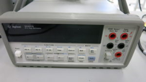
One problem with choosing closely matched resistors is that 0.1% of 1MΩ is 1kΩ. Most multimeters are rated in “digits”, e.g. “4 1/2 digits”. This means that they can display a range from 0 to 19999. This means that with a ~1MΩ resistor, you can measure ±50Ω steps. This is enough to measure resistor tolerance within 0.005%, but the more digits the better. Since I happened to have an HP 34401A 6 1/2 digit multimeter handy, I figured that overkill was the better part of valor.

HP Multimeter

Then, I set about sitting down and measuring the value of 30 resistors or so.

30 Resistors, poked in to anti-static foam so that I can correlate which resistor has which value in a written table.

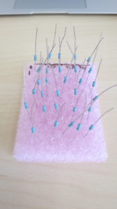
Once I had them all measured, I had to pick a set of closely matched resistors. Simply writing all the values down, it’s easy to pick a pair of closely matched resistors, but I needed two sets of eight closely matched resistors. The result was the following Matlab script, which picks the closest set of numbers from a group.

function [closestVals closestPos] = smallestSet(randomVals, number)

randomSize = size(randomVals);

if(randomSize(2) == 1)
    randomVals = randomVals.'
end

closestVals = randomVals(1:number);
closestPos = (1:number);
range(closestVals)
for value = randomVals
    if(value == -inf)
        continue;
    end
    nearVals = zeros(1,number);
    nearPos = zeros(1,number);
    distVals = abs(randomVals - value);
    for n = 1:number
        [minVal minPos] = min(distVals);
        nearVals(n) = randomVals(minPos);
        nearPos(n) = minPos;
        distVals(minPos) = inf;
    end
    
    if(range(nearVals) < range(closestVals))
        closestVals = nearVals;
        closestPos = nearPos;
    end
end

Using this script, I turned my random pile of 30 1% resistors into two sets of 8 resistors matched to better than 0.05%. While the value they are centered around is not exactly 970kΩ, the spread of values means that my CMRR does much better than a 1% priced pile of resistors should deliver, and it cost me a lot less than buying sixteen 0.05% matched resistors!

Electrocardiogram Input Protection Impedance (and CMRR)


Input protection in an electrocardiogram

When you’re building an electrocardiogram, one of the many layers of protection is making sure that there is a “dumb” resistor between the body of the patient and the inputs to the system. The reasoning for this is that there is not much that can go wrong with a resistor, and when it does, they generally fail open. This is a common sens protection similar to the requirement that a fuse be the first thing in line in any system past the power input, even before a power switch.

Since it is quite possible that your circuit will be connected to a human through a low impedance path (e.g. a wet electrode), these resistors protect the user against other failure modes. One might imagine, for example, an in circuit op-amp failing in such a manner that it simply directly connects the power rail of your system to the patient. Even in a low voltage 5V system, the low impedance and placement of wet electrodes means that you could be dumping tens of milliamps across the chest of a patient, potentially enough to stop a heart!

To protect against this, there should be high impedance in between the patient and circuit. The AAMI (Association for the Advancement of Medical Instrumentation) specifies 2.5MΩ input impedance. This is fairly conservative however, and higher impedance means more thermal voltage noise and more ambient noise pickup. A system with 1MΩ input resistors right at the input with ±9V supplies is only putting the patient at an absolute maximum 18µA of risk.

Okay, so easy: Throw some 1-2MΩ resistors at the input and we’re done, right? Nope!

Common Mode Rejection Ratio (CMRR)

Off the cuff, this might seem like no big deal. After all, your instrumentation amplifier has high input impedance, right? It’s supposed to be way higher than 1MΩ, so adding 1MΩ resistors shouldn’t make much difference.

In an ideal world, this is true. But it turns out that there’s this filthy little thing called manufacturing tolerances. One of the many magical things about integrated circuits is that, since all components are manufactured in close proximity in time and space, they tend to track together. This means that it is easy to get closely matched input impedance. This is critical because input resistance mismatch means that common mode signals — like the ubiquitous and dominant 50/60Hz line nose — get turned into differential mode signals, and amplified by your instrumentation amp, swamping out the signal you want to measure.

And the thing is, the whole point of using an instrumentation amplifier in the first place was to reject common mode signals!

Cheap resistors however,  are ±5% — actually 5% in each direction. Meaning 1MΩ is actually 950kΩ and 1.05MΩ.

Obviously, you can just pay money for closer matched resistors. Say 0.1% or even 0.001%. But that ends up being the price difference between 10¢ and $180! For a more modest 0.05%, you’re still looking at 75¢, which is reasonable for production, but sometimes you’re in a pinch and only need to build a prototype anyway.

And now we’re back to where I entered the picture. I was building an ECG system, and I needed a batch of input protection resistors. Eight of them, to be specific. The lab happened to have a bin of 970kΩ 1% resistors, and I am impatient.

My solution? Sort though the bin of 1% resistors and pick the closest matched set for my input leads, to minimize the impact on my system’s CMRR.

…to be continued.

The Best Desoldering Iron (for under $50)


There is an eternal debate among those of us who wield the iron, as to what the best way to go about desoldering components is. For surface mount components, I’d dare to say it’s a mostly settled question (I tread here at my own peril) with hot air rework stations being excellent and reasonably functional low cost units from china being widely available. I myself have one of these, which works reasonably well.

Figure 1: Sparkfun hot air rework station.

But when it comes to through hole components, the debate is much more raucous. Many people swear by application of their main iron and plain old solder wick. This was the first way to remove a soldered component that I was personally introduced to, and still find it a valuable tool in my kit.

Figure 2: Solder wick.

Others use so called “solder suckers” – either of the spring or bulb type.

Figure 3: Spring type solder sucker.

Figure 4: Bulb type solder sucker.

Personally, I’ve tried to use these on and off for years in a pinch in other people’s labs, and I have found them worse than garbage. I’ve never once successfully removed a component using one, but the heat I had to apply to try and keep the solder molten long enough to move the sucker in place has ruined many parts and pads under my watch. Never mind the awkwardness of tying to wrangle the component, sucker, and iron all at the same time.


I still remember the first time I was introduced to the “professional” solution to this problem. I was an undergraduate and I had soldered down some 16 pin dip that needed to be removed. The TA suggested I go ask the lab technician for use of his desoldering station, which was a concept I had not, to that point, considered.

Figure 5: Professional Weller desoldering station.

I still remember the sense of awe I had when I touched the iron to a pin, tapped a button, and the pin was clean. Voila!

Since then, I have been lucky enough to usually have access to them when I need them in professional environments, and I still aspire to own one someday – some day that I find one dirt cheap as surplus. But until then, I’ve found a pretty good alternative.

About ten years ago at Radio Shack, I found a bulb type desoldering iron, for about $17. I picked it up, skeptical, and brought it home. The next time I needed to remove a component, I plugged in this scraggly little iron. No temperature control and a rubber bulb. I was sure it would be garbage.

Figure 6: Bulb type desoldering iron.

But no, almost as easily as the professional irons, the bulb type iron took two passes to remove all the solder from a pin, but it worked. And more importantly, it worked without lifting a pad or driving a component to thermal death.

Figure 7: Vacuum tip.

Since then, it has been my go-to home solution for desoldering, and honestly, I’ve felt no severe need to shell out the cash for a professional Weller desoldering station.

In ten years since I got it, the price seems to have gone up by $6, but what appears to be the identical iron is still available at amazon (don’t worry, it’s not a referral link). Who knows, maybe the odd, still open Radio Shack even stocks them.