
Background
Every year I like to do some sort of artistic project as a gift. Historically they have been unique one-offs that I have yet to post here. This year however, I decided to do something a little more traditional — a Christmas ornament. I figured I could ‘mass produce’ them, and give one to everyone relevant, including sending them along with my annual holiday cards.
Given that I hail from Vegas, I decided that the way to go was to do a Christmas version of the famous ‘Welcome to Fabulous Las Vegas Nevada’ sign.

Circuit Design
The first challenge was coming up with a circuit. My primary requirement was that it should be able to last a whole season on a single coin cell (CR2032). Obviously, even with high efficiency LEDs, that would be nigh impossible, and giving up and going to 2AAs would have made the board too heavy to realistically hang on a tree.
I therefore decided that it would start to blink when triggered by a human somehow and would then shut off after a few seconds. I briefly considered using a passive infrared (PIR) motion sensor, which would have been affordable from the usual Chinese suspects on ebay, and would have met my power requirements (they can be incredibly low power in standby) but they also are rather bulky compared to size and weight requirements of an ornament.
The second (and obvious fallback option) would be a simple tactile switch. This has several advantages:
- Cheap
- Easy to implement
- Low parts count
Unfortunately, it has one fundamental flaw: To activate it requires a non-trivial amount of force. Not exactly a problem for most devices, but for an ornament dangling from a tree, it wouldn’t do, to require the user to grab and hold it (possibly with two hands) to make it do something. This left one more option: Touch switch.
The design is extremely simple — since I can afford to expose bare copper (well, tinned), I can float the base of a transistor to act as a switch when a touch to the exposed metal pulls the input to VCC
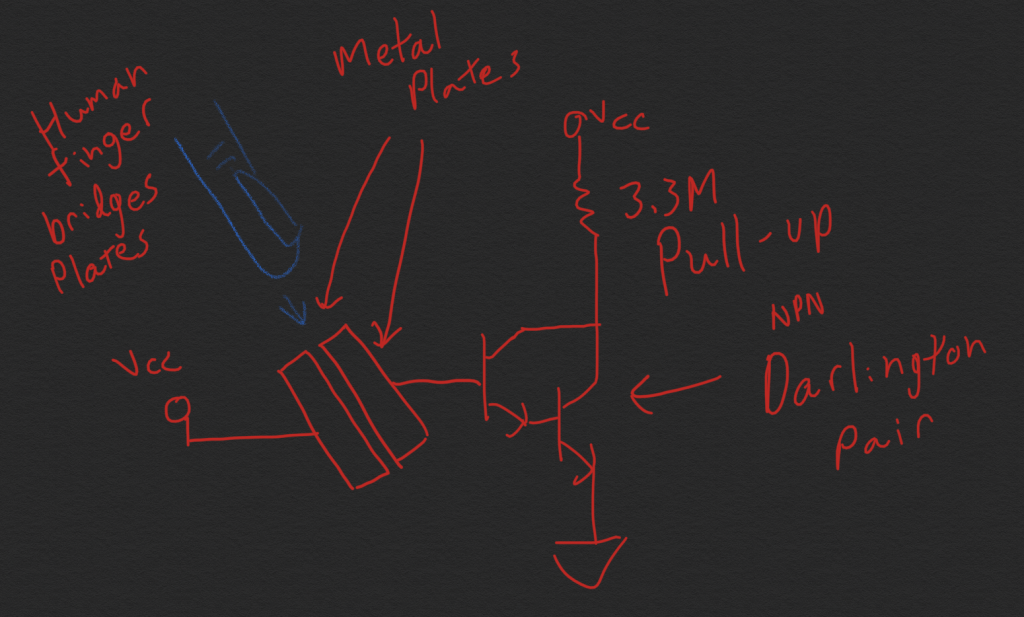
For the metal plates, I designed a pair on interdigitated polygons, as below, with one side pulled to VCC and the other connected to the base of the transistor.

Note that this design would not work with even the thinnest of gloves, is prone to corrosion, and might not even work for someone with extremely dry skin. BUT, it is cheap, simple, and extremely low power – wasting less than 1 µA quiescent current.
For the main circuit, I started out with an all analog design. The touch switch would have triggered a mono-stable oscillator, which turned on a bi-stable block, which in turn would drive the LEDs through a buffer transistor. There were several problems with this approach however.
- A jellybean 556 cannot run down to 2V (the dropout voltage for my single lithium cell) reliably.
- More sophisticated timer ICs are similarly priced (or more expensive) than a microcontroller.
- The standby current would at least as high as what I could achieve with a microcontroller in deep sleep.
Since I already had the tool chain set up to develop with the ATTINY85 microcontroller, I chose it – if I had more time to develop, I would likely have spun up the ATTINY10 (and indeed, I grabbed a handful of them) since they’re so low cost.
I chose run the ATTINY on its internal 1MHz oscillator, for absolute minimum power consumption. I also chose a variant which could run down to 1.8V, which would let me run my single CR2032 pretty much dry.
The final design, shown below was criminally simple. I tested it on a breadboard while I developed code and was able to drop it onto the PCB with (essentially) no changes.

I decided I was going for so low parts count that I even chose to omit the decoupling cap on the micro – I figured since it was the only active component, I could get away with saving the penny.
The biggest omission, however, was using only a single current limiting resistor for each color of LEDs. This is obviously bad practice and you should never, ever do this (TM), but given that my power supply is a high ESR lithium battery and the LEDs were grouped from a single batch on each board, I decided to take the risk. The reason for this is simple, it saved me 22 resistors and realistically, needing to find a way to handle a double sided load in the hobby reflow oven (or more realistically, soldering down by hand 4x as many components as I already was planning to, per board).
Code
Writing code for the ATTINY85 is almost criminally easy given that it is supported by the Arduino environment. Programming can be done with my trusty Sparkfun TinyAVR programmer, which I used with an SOIC adapter clip to program the SOIC parts I used in-circuit.
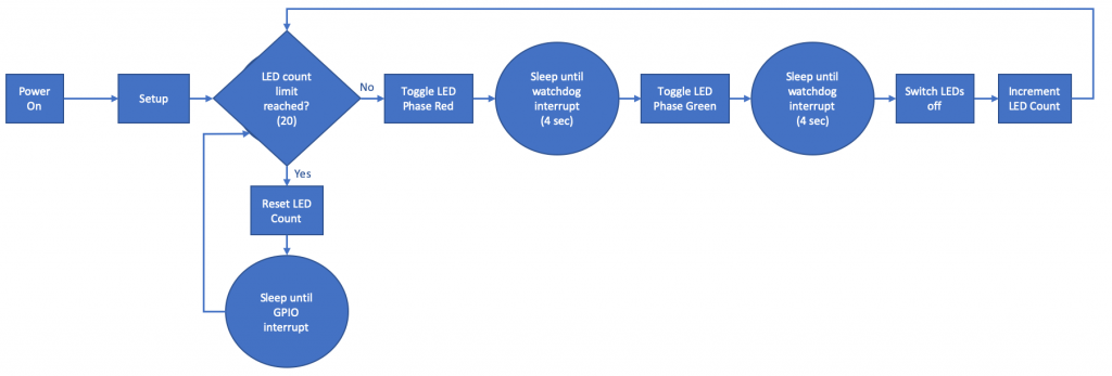
The underlying code is, unsurprisingly simple, but I am pleased with the design. After boot, the system goes to deep sleep (SLEEP_MODE_PWR_DOWN) until awoken by an external GPIO interrupt. When triggered, turns on one phase of the LEDs (e.g. red), goes back to sleep, after setting the watchdog timer, which awakens it a half-ish second later. On wake, it toggles to the alternate LED phase (to green or back to red), and repeats until the requisite number of cycles has been completed. Then it goes back to deep sleep.
The code can be found on GitHub here.
Layout
The layout is fairly straightforward. I laid out the board outline and silkscreen in inkscape, and then following various tutorials imported the outline and silkscreen into Eagle. Sizing the two correctly was a guess-and check experience. I didn’t take comprehensive notes on my import process, so unless someone asks for it, or I do it again next year, I’ll leave the details out of this post.
I am somewhat proud of removing all but a handful of visible vias and one trace on top of the board by hiding most of the vias underneath the LEDs.

Conclusion
I did take some measurements, and the device draws about 5mA while blinking and about 2µA when off (Not that much worse than the self discharge rate of the CR2032), so I’d call the design a roaring success. It certainly was a hit at the holidays!
This was a fun, quick and dirty Christmas ornament project and I will be revisiting it in the future. Expect a 2020 Christmas project post.