Introduction
What is UNIAC? It is the Ultimate Nixie Internet Alarm Clock.
It’s a Nixie alarm clock / boombox.
- It uses a Raspberry Pi to stream music from Spotify.
- It has integral IN-13 VU meters to visualize the music.
- It’s got a robot voice to relay information that the Nixies cannot.
- It’s got clickety light-up buttons on the front.
- It’s got a translucent clamshell case made of smoked acrylic.
It’s a piece of the future that never was. In short, it’s cool.
Motivation and Background
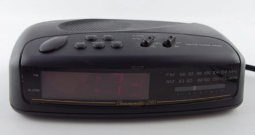
I built my first Nixie Clock in 2006, which worked, but I was never satisfied with the design. I soon began fantasizing about what my dream Nixie clock would look like. It would replace my dusty old RadioShack alarm clock.
Unfortunately, life got in the way. The project got shelved, and grad school came along, but the idea hung in the back of my mind. By 2015, the technology landscape had changed and my hands on electronics skills had grown. I had new options, and came up with a new plan using a RaspberryPi. The ultimate Nixie clock would have:
- Clock
- Alarm
- Calendar
- Spotify as the music/alarm source
To tackle this relatively complex project, I decided to break it into parts. After tackling each subsystem individually, I had a reliable, tested circuit and was able then to integrate them into a unified system.
Two Builds
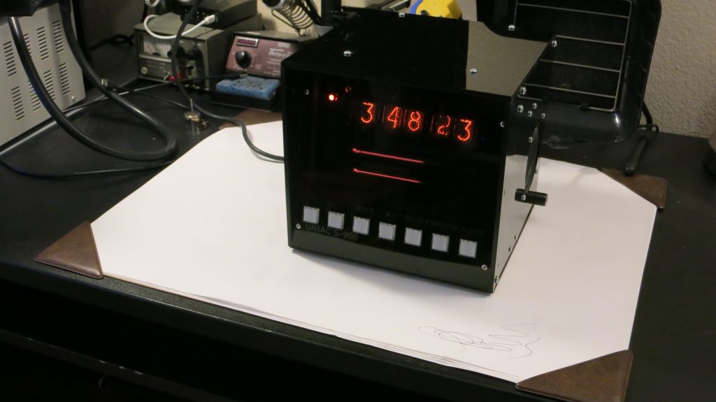
The first version was built in late 2015. It was a cube of laser cut acrylic sheets with the various subsystems mounted to an internal backplane with standoffs. The internal structure was built from square 3/8″ dowels which held the sides together. This version has served well on my electronics bench since it was put together, but it always bothered me that it was extremely cumbersome to open up and service. Additionally, the acrylic backplane was just inelegant.
In 2019, with this in mind I decided I could do better. I integrated all of the components (except the front panel buttons and speakers) onto a motherboard. With a single board, I decided on a boombox form factor. This version isn’t really a good fit for a bedside alarm clock, but it is extremely satisfying.
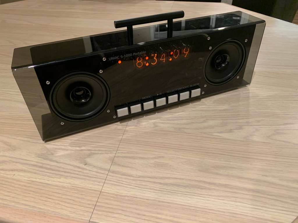
To enable this, I built an acrylic bending jig, and designed a clamshell case to hold it all. The case was made from two pieces of laser cut acrylic. The back panel is solid black to keep ambient light out. The front is smoked grey and hides the electronics but lets the Nixie goodness shine through.
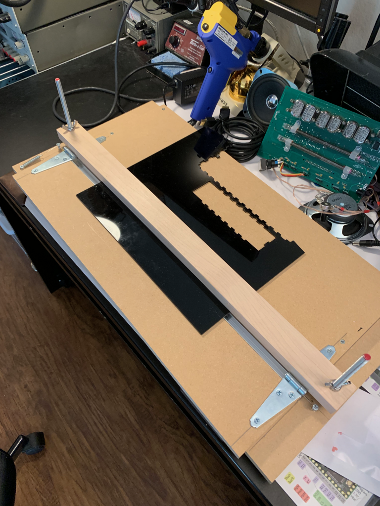
Getting the acrylic bent at the right spot took a few tries — the first test (using cheaper clear plastic) put the bend too close to the button cutouts. This caused the holes to deform and become teardrop shaped. I still think the clear case has a cool 90’s feel to it, but that doesn’t fit my general design tastes, so I stuck with the plan to go to a smoked front panel.
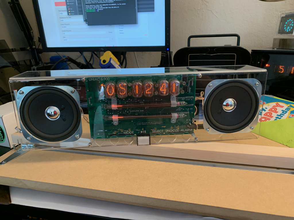
After a couple of revisions, the final two piece enclosure came together nicely. I was worried that lifting the unit by the handle would cause the acrylic to flex, but it’s actually reasonably sturdy. I might consider some additional brackets to more firmly attack the front to the back in the future. For now, I think mounting the two haves together through motherboard standoffs is sufficient.
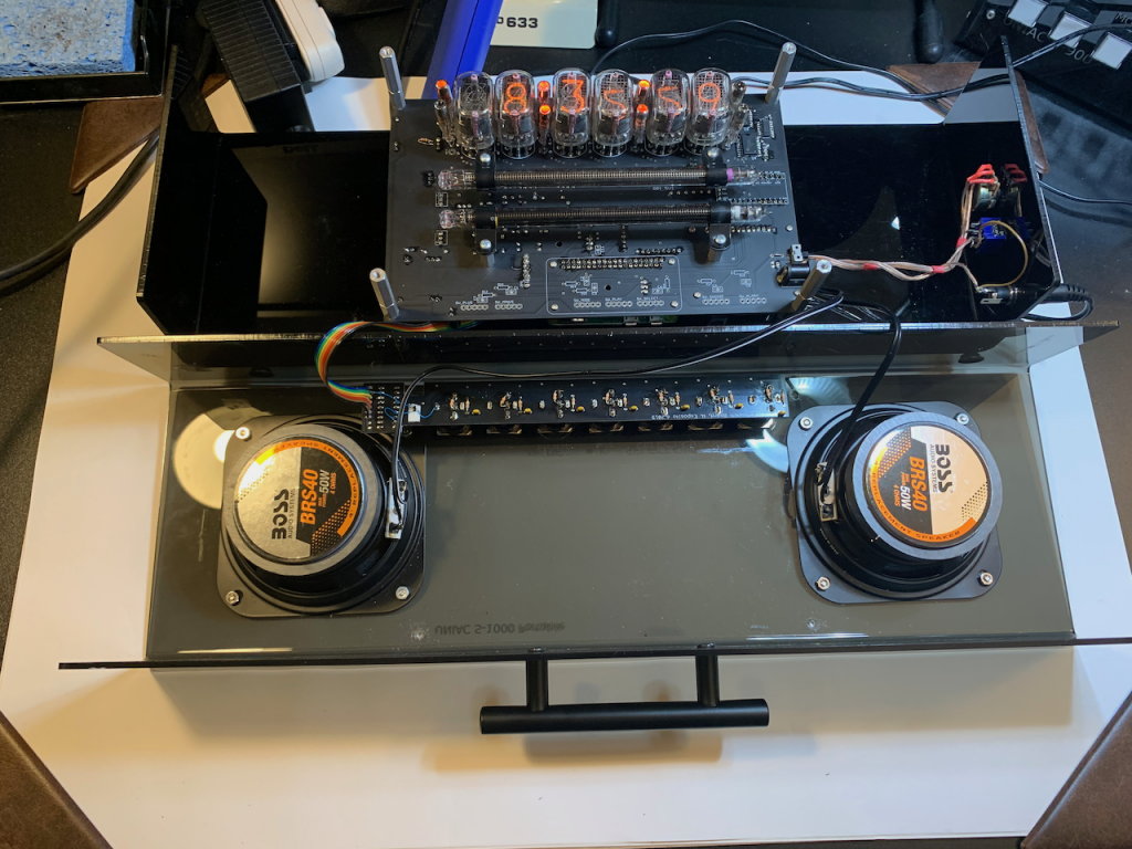
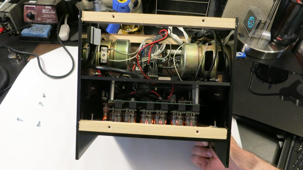
UNIAC 2019 showing the clamshell case open, with the motherboard and button board.
The VU-Meter
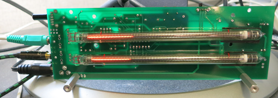
When audio is playing from UNIAC, it really needed to show some “activity” — something like an oscilloscope would work, but in keeping with the Nixie theme, I decided to use the IN-13 bargraph tubes to display the sound levels on the left and right channels. No digital trickery here, the module takes analog line-level audio as a passthrough and displays the amplitude level of the audio channels on its IN-13 bargraph tubes. I’ve seen lots of mono IN-13 VU-meters, and I’ve seen a few standalone modules, but I’ve never seen them combined with normal Nixies before.
While I originally designed the VU-meter module intending to use it as a drop in component in UNIAC, the circuit has seen more service hours as a standalone module in my hi-fi (it’s been in near-constant use since late 2015). Nonetheless, it looks great in its intended role as a component of UNIAC.
I described the design of this component in detail in a series of previous posts, which includes some theory, design decisions, and schematics.
The Nixie Display
Because UNIAC is a media player, it needed a general purpose addressable Nixie display, not just a Nixie clock module. This part of the project was actually the first I began to tackle, back in 2009. I had nearly finished a display module using an 8051 and written in assembly, but stopped work when I went back to school. With cross-fading and all sorts of neat features, it was more or less what I wanted, but it had minor ghosting issues that I was unwilling to tolerate. Therefore, version one (2015) used Smart Nixie modules from Taylor Edge with a modified backplane.
For the final version (2019), I based the design off a four tube Nixie display module using a Teensy 3.2 I had built for another project. When I finish that project, I will describe it in detail in a post. Until then, you can see the prototype at the right. The chief advantages to this design are a reduction in cost versus six Smart Nixie sockets, and the ability to integrate it onto the new motherboard without using risers. The UNIAC version of the display supports six tubes and uses IN12As, but is otherwise broadly the same design.
Input is via USB serial, TTL serial or i2c inputs and supports both dimming and crossfading.
Admittedly, multiplexing by 6x instead of 4x leads to a slightly dimmer display than the previous Smart Nixie approach, but it’s good enough. If there’s a future build, I’ll likely split it up into two banks of three tubes to increase the brightness (at the cost of board area and complexity).
The Motherboard
With the Nixie display circuit and the vu-meter circuit validated, it was time to build a full system.
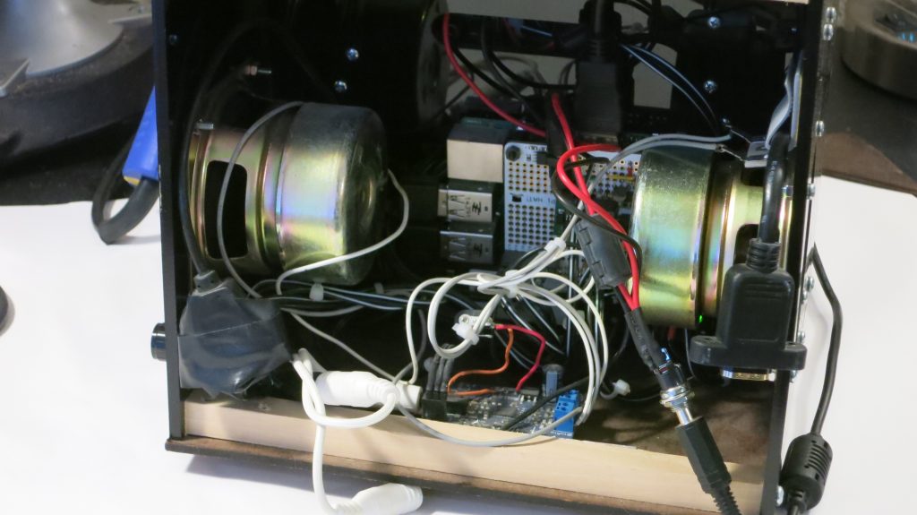
Version 1, built in 2015 prototype was a ‘wired together modules’ build. Using a laser cut backplane, the various modules were mounted to both sides with standoffs. The backplane then slotted into a cube made with an internal wooden frame covered with laser cut panels. This design worked well, but the rats nest of wires made it an absolute nightmare to open up and work on.
For the final version, I decided I had to replace the backplane board with a PCB. The new motherboard would have an integrated copy of the Nixie display and vu-meter circuitry. A footprint The Raspberry Pi, audio DAC, and amplifier would be on board as well. It would take 12V in, and the only off board connections would be the speakers and to the front panel buttons. Because all my peripherals used serial interfaces, the actual board design was actually pretty sparse, and most of the work was in routing the traces for the Nixie display in a way that maintained sufficient creepage.
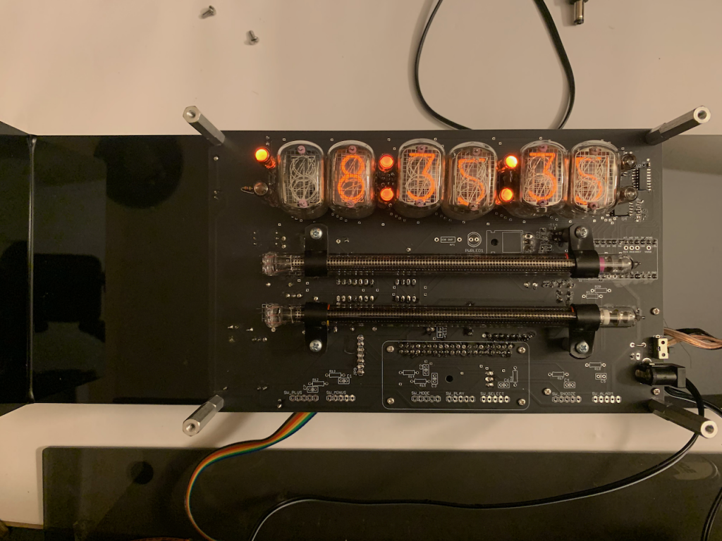
Taking a look at the front side of the motherboard (above), it’s primarily the cosmetic components. We see the six IN-12A tubes, eight INS-1 neon bulbs, two IN-13 tubes. Also of note are the unpopulated pads along the bottom for connecting the buttons directly to the RaspberryPi, which are unused in this build in favor of the i2c button board (described in the next section).
A Tour of the Motherboard
On the back side of the board, we can see a ton of components.
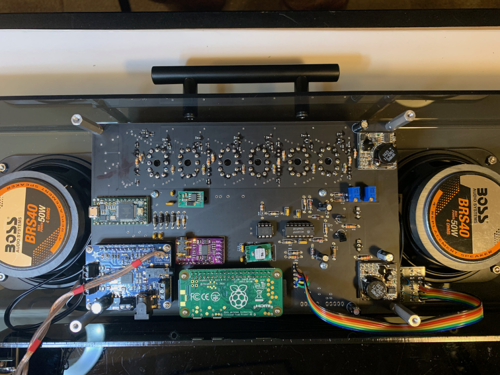
Next, in green with a raspberry symbol, is the main CPU, a RaspberryPi Zero W (hereafter RPi), which is the core of the system.
To the right of that is a rainbow ribbon cable going off to the button board.
Next, at the right is a TES-1364H boost module. This provides HV for the IN-13s. It is twinned with another -1364 at the top right, which provides HV for the numbers. I chose to keep the two supplies separate not because I was sure I was out of current, but because the two sets of tubes call for different striking voltages, and I didn’t feel like adjusting the values of the two display circuits to compensate. In a future revision, I’ll absolutely address that.
The group of components just right of center are the components for the IN-13 display, which are described in more detail in the IN-13 VUMeter posts, but the two DIP ICs are a quad op-amp and an ATTINY85.
The two tiny green three-pin boards are Mu-rata OKI-78SR modules. These are more efficient drop in replacements for the classic LM7805.
Directly above the RPi is a purple board. This is the i2s sound card using the PCM5102A ic.
Connected to the sound card is a blue Adafruit class-d amplifier board at the bottom left. It was chosen because it is relatively low-noise, has a mute pin, and can use an external pot for volume control — here you can see the wire for the pot running off to the knob on the side of the rear panel.
Finally at the top left is a Teensy 3.2, the CPU for the Nixie display module. This is gross overkill to drive a display, but it was convenient to code up quickly, and I was able to set it up as an i2c slave, simplifying communication with the RPi.
The Button Board
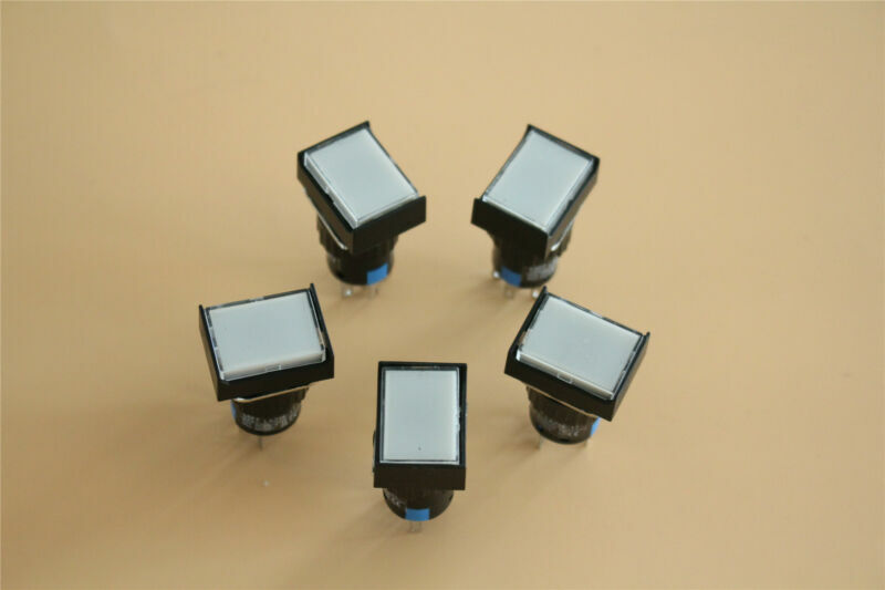
For the control panel interface I chose some clicky 12V illuminated momentary buttons that were intended for industrial applications. Very satisfying. They were about $1.30 per each, so not cheap, however. Given that the buttons are the main user interface, having something that satisfies the retro vibe satisfactorily was worth it.
The 2015 version used a single GPIO pin on the raspberry pi for each button, and used a single GPIO (through a FET, obviously) to switch the lighting on them all on together. This, again, led to a tedious amount of manual wiring, so I designed a button board using a MCP23017 GPIO expander to connect to the buttons. The board itself is very simple, although I had the first boards manufactured by AllPCB, and they failed to route the slots, despite saying they’d confirm the slots with checkplots in an email discussion beforehand. This triggered my switch to PCBWay who correctly provided checkplots and produced the right board. I have been using them since, and who have treated me well — no they aren’t sponsoring me, I’m just pissed off enough at AllPCB to mention it, since they ignored my customer complaint that I filed after the fact.
The Battery Problem
Okay, it’s time for full disclosure, I’ve been calling this project portable, but throughout the build process I treated a battery as “something I would figure out later” — It turns out the BMSs are no joke, and there wasn’t much out there that would suit my needs. The fundamental problem is that there’s a large burst of current on power up, despite the fact that the overall system only draws a few hundred mA when fully up and running. I tried a few low cost boost converters and they all browned out before the system booted. As I wanted to share the portable UNIAC with my friends at PAX 2019, I ended up punting last minute and taping a 12V battery pack from Amazon to the back of the unit.
Music Playback
To play music, I am using the command line media player Mopidy and its Spotify plugin, Mopidy-Spotify. This requires a premium Spotify account to work, and is brittle. The API Mopidy-Spotify uses is not supported anymore. I’ve found that the repo fails to load my playlists unless I use the fork mentioned in this thread.
Getting the audio itself to work was also a massive pain, as the various Linux audio subsystems like to fight as is, and the I2S audio card I was using made things more difficult. I could go into more detail here, but I think it merits its own post…
So I wrote a full post about it!
Display Library
For the first version of the UNIAC with TES SmartNixie modules, I whipped up a quick python library to interface with them. It might come in handy for someone else, so I have published it here.
For the final version, I was using my own i2c display module, so I wrote a (nearly) drop-in replacement library for the SmartNixie library, so I could minimally modify the main UNIAC application to support the new display. It is published here.
It supports some fun features like dimming, cross-fading, blanking, and blinking.
The UNIAC Application
The main UNIAC application is a python script. The main loop probes the interface buttons and then calls a python god object, which maintains various states, drives the displays and voice, and sends audio commands to Mopidy. There’s a lot to this application, but that’s an entire post in and of itself. Until I get around to a full writeup for it, you can find it published here.
Conclusion
At the end of the project, UNIAC is probably the most satisfying hobby project I have yet made. Due to the brittle nature of the Mopidy-spotify, my next task is to move the Spotify interface to spotifyd, which I discovered due to reading Dino Fizotti’s excellent Diskplayer writeup. The other glaringly obvious improvement is adding a proper, internal battery system.
Longer term, I’d like to try to integrate it with a voice assistant to really supercharge interface, but that is more software work than I’m willing to take on in the immediate future.
The sad irony however, is that I’ve spent so long listening to the crappy buzzer of my Radio Shack alarm clock that I actually don’t want to give it up now. I’m conditioned to wake up to it quickly, and it takes up little space on my nightstand. Oh well. Maybe the next project will be a UNIAC Mini with an alarm buzzer feature.
I know this has been a long post. Thanks for sticking with me!
o/
Hey can do you have a list of all the components you used and where to get them?
Sadly, I don’t have a full BOM, sorry. It’s something I should put together though. I’ll try to put one together for a follow up post!
Definitely interested in the full list of items. Will be waiting
Congratulations, it looks wonderful!
I too would love the BOM.
And if I could be a bit greedy, I would love to watch you build another one, step by step!
This is such a cool blend of tech/classic, only an artist could envision something this cool.
Plus, you’re obviously a smart and cool engineer!
Awesome job!