IV-11 Thermometer Software


Processor

Okay, so the one piece of hardware that hasn’t been much discussed in this chain is the processor. I chose an atmega 328p for a couple of reasons:

  1. I can use the massive stock of Arduino libraries and IDE. For a simple project like this, where the complexity management of “adult” IDEs won’t be very useful, it’s the right tool for the job.
  2. I happen to have a USBTiny ISP board for in circuit programming. By dropping the atmega into the socket on an Arduino UNO and using its ISP port, I can program the micro without assembling ISP pins on my breadboard.
  3. I had a drawer full of atmega 328Ps.

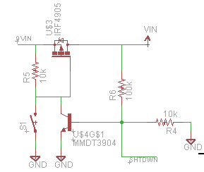
With the decision made, I set out to use the atmega on a breadboard, as laid out here. Since I’m lazy and didn’t want to lay down a crystal or capacitors, and I need next to no performance, I opted to use the internal 8MHz oscillator.

Unlike the tutorial, I simply socketed the atmega into an unused UNO and plugged it in to my Sparkfun AVR Programmer. After burning the bootloader and program, I dropped it in to my breadboard and went with it. This is the first time I’ve used the 8MHz oscillator and it did exactly what it said on the tin.
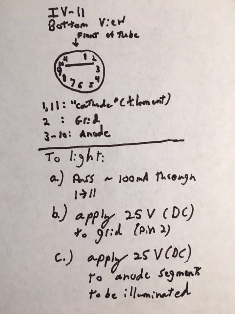
VFD Support

To drive the VFD, I initially tried to use a pre-made seven segment library, SevenSeg. Despite the fact that it looks like it should work, I couldn’t get it to turn on the display. Given that I wasn’t using any of the complex features, like multiplexing, I decided to save time bit-bang the pins myself.

The resulting functions were as follows:

#define SEG_A 0
#define SEG_B 1
#define SEG_C 2
#define SEG_D 3
#define SEG_E 4
#define SEG_F 5
#define SEG_G 6
#define SEG_DP 7
#define PWR 12
int pinDefinitions[8] = {SEG_A, SEG_B, SEG_C, SEG_D, SEG_E, SEG_F, SEG_G, SEG_DP}; //array of pin segments
byte charArray[10] = { //array of segments to light up for each digit 0-9
  0b11111100,
  0b01100000,
  0b11011010,
  0b11110010,
  0b01100110,
  0b10110110,
  0b10111110,
  0b11100000,
  0b11111110,
  0b11100110
};
void initSegPins(int* pins) //initialize the pins
{
  for(int i = 0; i < 8; i++)
  {
    pinMode(pins[i], OUTPUT);
  }
}

void setDisplay(int num, int* pins) //draw a digit 0-9 on pins
{
  num = num % 10;
  byte segments = 0x00;
  writeArb(charArray[num], pins);

}

void writeArb(byte segments, int* pins) //draw an arbitrary byte on pins
{
  for(int i = 0; i < 8; i++)
  {
    digitalWrite(pins[i], (segments>>(7-i))&0x01);
  }
}
void setDisplay(char c, int* pins) //draw a character on the pins
{
  if((c > 0x2F) && (c < 0x3A)) //digit 0-9
  {
    setDisplay((int) c - 0x30, pins);
  }
  else
  {
    switch(c) {
      case 'f':
      case 'F':
        writeArb(0b10001110, pins);
        break;
      case 'c':
        writeArb(0b00011010, pins);
        break;
      case 'C':
        writeArb(0b10011100, pins);
        break;
      case 'd':
        writeArb(0b01111010, pins);
        break;
      case 'D':
        writeArb(0b11000110, pins);
        break;
      case 'h':
        writeArb(0b00101110, pins);
        break;
      case 'H':
        writeArb(0b01101110, pins);
        break;
      case 'b':
        writeArb(0b00000000, pins);
        break;
    };
  }
}
void printNum(float num, int* pins, int delayLen = 500) //print a number up to 999, rounded to nearest int
{
  num = round(num);
  if(num > 100)
  {
    setDisplay(int(floor(num/100))%1000, pins);
    delay(delayLen);
  }
  if(num > 10)
  {
    setDisplay(int(floor(num/10))%100, pins);
    delay(delayLen);
  }
  setDisplay(int(floor(num))%10, pins);
  delay(delayLen);
}

Temperature Sensor

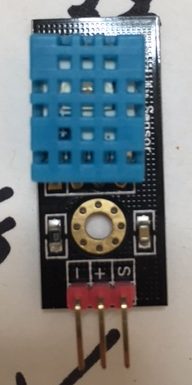
The final piece of the puzzle was the DHT11 temperature sensor. Since I didn’t have one on hand, this represented the only cash expenditure for this project — $10 at Fry’s. I grabbed on OSEPP DHT11 breakout board, since it was what they had. It had the advantage of getting humidity as well, so I made the program report that in addition to temperature. Fortunately, Adafruit also sells DHT11s, so I was able to use their library, although I did need to also install their general sensor library. These libraries are the real perk of using the Arduino environment, admittedly.

The final code for the entire program is here:

#include "DHT.h"

#define DHTPIN 13     // what digital pin we're connected to

// Uncomment whatever type you're using!
#define DHTTYPE DHT11   // DHT 11

// Initialize DHT sensor.
// Note that older versions of this library took an optional third parameter to
// tweak the timings for faster processors.  This parameter is no longer needed
// as the current DHT reading algorithm adjusts itself to work on faster procs.
DHT dht(DHTPIN, DHTTYPE);


#define SEG_A 0
#define SEG_B 1
#define SEG_C 2
#define SEG_D 3
#define SEG_E 4
#define SEG_F 5
#define SEG_G 6
#define SEG_DP 7
#define PWR 12
int pinDefinitions[8] = {SEG_A, SEG_B, SEG_C, SEG_D, SEG_E, SEG_F, SEG_G, SEG_DP}; //array of pin segments
byte charArray[10] = { //array of segments to light up for each digit 0-9
  0b11111100,
  0b01100000,
  0b11011010,
  0b11110010,
  0b01100110,
  0b10110110,
  0b10111110,
  0b11100000,
  0b11111110,
  0b11100110
};
void initSegPins(int* pins) //initialize the pins
{
  for(int i = 0; i < 8; i++)
  {
    pinMode(pins[i], OUTPUT);
  }
}

void setDisplay(int num, int* pins) //draw a digit 0-9 on pins
{
  num = num % 10;
  byte segments = 0x00;
  writeArb(charArray[num], pins);

}

void writeArb(byte segments, int* pins) //draw an arbitrary byte on pins
{
  for(int i = 0; i < 8; i++)
  {
    digitalWrite(pins[i], (segments>>(7-i))&0x01);
  }
}
void setDisplay(char c, int* pins) //draw a character on the pins
{
  if((c > 0x2F) && (c < 0x3A)) //digit 0-9
  {
    setDisplay((int) c - 0x30, pins);
  }
  else
  {
    switch(c) {
      case 'f':
      case 'F':
        writeArb(0b10001110, pins);
        break;
      case 'c':
        writeArb(0b00011010, pins);
        break;
      case 'C':
        writeArb(0b10011100, pins);
        break;
      case 'd':
        writeArb(0b01111010, pins);
        break;
      case 'D':
        writeArb(0b11000110, pins);
        break;
      case 'h':
        writeArb(0b00101110, pins);
        break;
      case 'H':
        writeArb(0b01101110, pins);
        break;
      case 'b':
        writeArb(0b00000000, pins);
        break;
    };
  }
}
void printNum(float num, int* pins, int delayLen = 500) //print a number up to 999, rounded to nearest int
{
  num = round(num);
  if(num > 100)
  {
    setDisplay(int(floor(num/100))%1000, pins);
    delay(delayLen);
  }
  if(num > 10)
  {
    setDisplay(int(floor(num/10))%100, pins);
    delay(delayLen);
  }
  setDisplay(int(floor(num))%10, pins);
  delay(delayLen);
}
void setup() {
  // put your setup code here, to run once:
  initSegPins(pinDefinitions);
  digitalWrite(PWR, HIGH);
  pinMode(PWR, OUTPUT);
  dht.begin();
  delay(500);

// Read temperature as Fahrenheit (isFahrenheit = true)
  float f = dht.readTemperature(true);
  printNum(f, pinDefinitions);
  //print degree symbol and F
  setDisplay('D', pinDefinitions);
  delay(500);
  setDisplay('f', pinDefinitions);
  delay(500);

  //blank display
  setDisplay('b', pinDefinitions);
  delay(500);
  
  float h = dht.readHumidity(); //humidity
  printNum(h, pinDefinitions);
  setDisplay('H', pinDefinitions);
  delay(500);
  
  //turn off system
  digitalWrite(PWR, LOW);
  
}


void loop() {

}

Conclusion

So, what does the final project look like? Like this!

What is it showing? The temperature (two digits), then the degrees symbol and F. This is followed by a pause, then it reports percent humidity and the letter H (for humidity).

That’s all folks! Hope you enjoyed the read. On to the next project.

Controlling the IV-11


Okay, so power problems solved, it was time to address the control issue.

Filament Driver

The first problem was driving the filament. The filament is roughly 12Ω and it is recommended to drive at 1.5V and about 100mA. There is scant information online, and that which I have found suggests things like using several diode drops or a zener diode from a 5V supply to get 1.5V, a current limiting resistor, or the like.

Giving it some thought, I decided to take a different approach: current control. Taking a page from LED control, I used a classic constant current supply circuit, as shown below.

Filament Driver Circuit

The 6Ω resistor sets the current of the driver, which is rougly I_load = 0.6V / R_Set where 0.6V is the turn on of the NPN control transistor. To turn on, the FET must have a Vgs < Vcc (5V in this case). Since the power dissipated by the FET is  P = I_load (0.1A) * Vds, and without the 22Ω resistor, it would be: Vds = Vcc-0.6-V_load = 5 – 0.6 – 1.2 = 3.2V

Thus, the FET would be dissipating 0.1 * 3.2 = 0.32W. To alleviate that, the 22Ω dropper resistor is placed in series with the load, resulting in Vds = Vcc – 0.6 – 2.2 – V_load = 5 – 0.6 – 2.2 – 1.2 = 1V meaning the FET will dissipate 0.1W and the 22Ω resistor will dissipate 0.22W.

Thus, we can be confident of the current that will be passing through our filament even if something goes haywire with the power supplies.

Anode Control

To control the actual segments of the VFD, we have to pull each anode to +25V. Obviously, our microcontroller cannot do this, and cannot handle exposure to 25V levels in any case. Fortunately, unlike Nixies, where the approximately 200V levels are far too high for “jellybean” transistors to handle, 25V is well within the 40V range of classis 2N2904/2N3906 NPN/PNP transistors. Therefore, we can use a standard high side switch circuit to control the anodes, driving each pin with the GPIO of our microcontroller.

Anode driver circuit.

Temperature Sensor

The final part of the circuit is the temperature sensor. I used an off the shelf OSEPP DHT11 module that I found at Fry’s — it only takes Vcc (5V), GND, and a signal pin, and I used the standard Adafruit DHT11 library to communicate with it. More on that (and the software in general) in the next post.


Osepp DHT11 Temperature Sensor

Powering the IV-11


In our last adventure, we lit the IV-11 with benchtop power supplies. Nice to show that we know how it works. Now, it’s time to build a project around it. After some thought about what I would like to display with a single digit seven segment display, I chose a thermometer. Taking up a wall outlet doesn’t make much sense either, so it would have to be battery powered and fairly energy efficient. To drive the IV-11, I’d need a 25V supply as well. Fortunately, in my parts bin, I had a couple of tricks up my sleeve. First, I had a handy $2 boost supply from china. I also had a spare Murata 7805 replacement, which provides a drop in replacement for the classic LM7805 linear regulator, but at a higher efficiency (and without the strict need for the off board filter caps)!

Boost mode power supply from eBay to make the 25V supply rail from a battery source.


The 5V rail would provide power for several things. Most obviously, it would supply power to the microprocessor (an Atmega 328P) and sensor (a DHT11 module from OSEPP, picked up at my local Fry’s — more on that in a later post). Additionally, the 5V rail would provide power for the filament — this would be more efficient than some sort of resistor divider down from 25V.

The final part of the power supply would be the soft power module. It’s a circuit I’ve used before, based off the Dave Jones soft power switch.

My modification omits the hardware “power off” functionality — the button latches the power supply on, and the microcontroller has the ability to switch the circuit off by pulling a GPIO pin low.

Soft power supply with microcontroller shutdown.

Using this power switch, the system can be turned on by a user pressing the power button, run its temperature measurement routine, and shut itself off, using absolutely no standby power.

I had originally hoped that I could use a couple of lithium coin cell batteries to power this, but I realized that I’d be taking a couple hundred milliamps at full draw. Clearly, this wasn’t in the cards for lithium batteries, which have high internal resistance. Nonetheless, a single 9V battery ended up being a reasonable compromise.

The IV-11 VFD


A couple of years ago (yes, years) I was given an IV-11 VFD tube. VFDs are a class of tube that is less popular among hobbyists than the more beloved orange Nixie tube — although they are often mistaken for them by newbies.

An unlit IV-11 tube, courtesy of tubes-store.com

Having no idea just how to drive the tube, I dropped it into the bottom of my Nixie parts bin (ironic, admittedly). There it languished until about three weeks ago, when I decided I needed a weekend project and would like to try and build a circuit around it. Step one was to figure out if I could light the tube.

Fortunately, the ever handy Dieter’s Tube Archive had a translated datasheet. Important because the tubes are surplus from the Soviet Union, meaning that the original datasheet was in Russian!

With a datasheet in hand, I knew the voltages and currents needed, so I was off to the races. Taking the pinout from the datasheet, shown below,

Pinout of the IV-11 as given by the Dieter’s datasheet.

I switched on my two trusty benchtop power supplies (both are single output), set my voltage and current limits, and was all set to go… or so I thought.

IV-11, in real life, with the pins clearly visible.

Here’s where reality and the datasheet collide. The datasheet says there is a “short pin 12”. In reality, there is no pin 12 at all, just a gap. Alright, that’s a warning sign, but not the end of the world. The gap however, means that the datasheet view of the bottom of the tube has the rotation at about 45 degrees. It also took me some time (and observation of the internal construction of the tube) to determine that this pinout was a bottom view of the tube, not the top. To save the rest of you the time I wasted making heads or tails of this, here’s my IV-11 pinout.

Bottom view of the IV-11 tube, with the digit facing the top of the image. Pin numbers run clockwise, with pins 1 and 11 being the filament, 2 the grid, and 3-10 being anode segments.


To finish my testing, I simply connected the appropriate anode segment to 25V to light it. I was going to include a picture here of the VFD lit this way. Thing is…I didn’t take a picture of it lit back then, and when writing this post, I managed to blow it up by swapping pins 1 & 2 with my alligator clips. On the plus side, the filament made a really bright lightbulb for a few hundred milliseconds. Oh well, they’re only $3/ea on eBay from the US. Way less if I’m willing to wait for shipping from Russia. At this point, I’m invested enough to buy a couple more.

Sorting Resistors


One problem with choosing closely matched resistors is that 0.1% of 1MΩ is 1kΩ. Most multimeters are rated in “digits”, e.g. “4 1/2 digits”. This means that they can display a range from 0 to 19999. This means that with a ~1MΩ resistor, you can measure ±50Ω steps. This is enough to measure resistor tolerance within 0.005%, but the more digits the better. Since I happened to have an HP 34401A 6 1/2 digit multimeter handy, I figured that overkill was the better part of valor.

HP Multimeter

Then, I set about sitting down and measuring the value of 30 resistors or so.

30 Resistors, poked in to anti-static foam so that I can correlate which resistor has which value in a written table.

Once I had them all measured, I had to pick a set of closely matched resistors. Simply writing all the values down, it’s easy to pick a pair of closely matched resistors, but I needed two sets of eight closely matched resistors. The result was the following Matlab script, which picks the closest set of numbers from a group.

function [closestVals closestPos] = smallestSet(randomVals, number)

randomSize = size(randomVals);

if(randomSize(2) == 1)
    randomVals = randomVals.'
end

closestVals = randomVals(1:number);
closestPos = (1:number);
range(closestVals)
for value = randomVals
    if(value == -inf)
        continue;
    end
    nearVals = zeros(1,number);
    nearPos = zeros(1,number);
    distVals = abs(randomVals - value);
    for n = 1:number
        [minVal minPos] = min(distVals);
        nearVals(n) = randomVals(minPos);
        nearPos(n) = minPos;
        distVals(minPos) = inf;
    end
    
    if(range(nearVals) < range(closestVals))
        closestVals = nearVals;
        closestPos = nearPos;
    end
end

Using this script, I turned my random pile of 30 1% resistors into two sets of 8 resistors matched to better than 0.05%. While the value they are centered around is not exactly 970kΩ, the spread of values means that my CMRR does much better than a 1% priced pile of resistors should deliver, and it cost me a lot less than buying sixteen 0.05% matched resistors!

Electrocardiogram Input Protection Impedance (and CMRR)


Input protection in an electrocardiogram

When you’re building an electrocardiogram, one of the many layers of protection is making sure that there is a “dumb” resistor between the body of the patient and the inputs to the system. The reasoning for this is that there is not much that can go wrong with a resistor, and when it does, they generally fail open. This is a common sens protection similar to the requirement that a fuse be the first thing in line in any system past the power input, even before a power switch.

Since it is quite possible that your circuit will be connected to a human through a low impedance path (e.g. a wet electrode), these resistors protect the user against other failure modes. One might imagine, for example, an in circuit op-amp failing in such a manner that it simply directly connects the power rail of your system to the patient. Even in a low voltage 5V system, the low impedance and placement of wet electrodes means that you could be dumping tens of milliamps across the chest of a patient, potentially enough to stop a heart!

To protect against this, there should be high impedance in between the patient and circuit. The AAMI (Association for the Advancement of Medical Instrumentation) specifies 2.5MΩ input impedance. This is fairly conservative however, and higher impedance means more thermal voltage noise and more ambient noise pickup. A system with 1MΩ input resistors right at the input with ±9V supplies is only putting the patient at an absolute maximum 18µA of risk.

Okay, so easy: Throw some 1-2MΩ resistors at the input and we’re done, right? Nope!

Common Mode Rejection Ratio (CMRR)

Off the cuff, this might seem like no big deal. After all, your instrumentation amplifier has high input impedance, right? It’s supposed to be way higher than 1MΩ, so adding 1MΩ resistors shouldn’t make much difference.

In an ideal world, this is true. But it turns out that there’s this filthy little thing called manufacturing tolerances. One of the many magical things about integrated circuits is that, since all components are manufactured in close proximity in time and space, they tend to track together. This means that it is easy to get closely matched input impedance. This is critical because input resistance mismatch means that common mode signals — like the ubiquitous and dominant 50/60Hz line nose — get turned into differential mode signals, and amplified by your instrumentation amp, swamping out the signal you want to measure.

And the thing is, the whole point of using an instrumentation amplifier in the first place was to reject common mode signals!

Cheap resistors however,  are ±5% — actually 5% in each direction. Meaning 1MΩ is actually 950kΩ and 1.05MΩ.

Obviously, you can just pay money for closer matched resistors. Say 0.1% or even 0.001%. But that ends up being the price difference between 10¢ and $180! For a more modest 0.05%, you’re still looking at 75¢, which is reasonable for production, but sometimes you’re in a pinch and only need to build a prototype anyway.

And now we’re back to where I entered the picture. I was building an ECG system, and I needed a batch of input protection resistors. Eight of them, to be specific. The lab happened to have a bin of 970kΩ 1% resistors, and I am impatient.

My solution? Sort though the bin of 1% resistors and pick the closest matched set for my input leads, to minimize the impact on my system’s CMRR.

…to be continued.