Okay, so power problems solved, it was time to address the control issue.
Filament Driver
The first problem was driving the filament. The filament is roughly 12Ω and it is recommended to drive at 1.5V and about 100mA. There is scant information online, and that which I have found suggests things like using several diode drops or a zener diode from a 5V supply to get 1.5V, a current limiting resistor, or the like.
Giving it some thought, I decided to take a different approach: current control. Taking a page from LED control, I used a classic constant current supply circuit, as shown below.
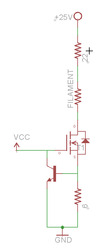
The 6Ω resistor sets the current of the driver, which is rougly I_load = 0.6V / R_Set where 0.6V is the turn on of the NPN control transistor. To turn on, the FET must have a Vgs < Vcc (5V in this case). Since the power dissipated by the FET is P = I_load (0.1A) * Vds, and without the 22Ω resistor, it would be: Vds = Vcc-0.6-V_load = 5 – 0.6 – 1.2 = 3.2V
Thus, the FET would be dissipating 0.1 * 3.2 = 0.32W. To alleviate that, the 22Ω dropper resistor is placed in series with the load, resulting in Vds = Vcc – 0.6 – 2.2 – V_load = 5 – 0.6 – 2.2 – 1.2 = 1V meaning the FET will dissipate 0.1W and the 22Ω resistor will dissipate 0.22W.
Thus, we can be confident of the current that will be passing through our filament even if something goes haywire with the power supplies.
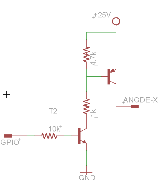
Anode Control
To control the actual segments of the VFD, we have to pull each anode to +25V. Obviously, our microcontroller cannot do this, and cannot handle exposure to 25V levels in any case. Fortunately, unlike Nixies, where the approximately 200V levels are far too high for “jellybean” transistors to handle, 25V is well within the 40V range of classis 2N2904/2N3906 NPN/PNP transistors. Therefore, we can use a standard high side switch circuit to control the anodes, driving each pin with the GPIO of our microcontroller.
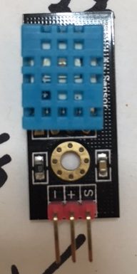
Temperature Sensor
The final part of the circuit is the temperature sensor. I used an off the shelf OSEPP DHT11 module that I found at Fry’s — it only takes Vcc (5V), GND, and a signal pin, and I used the standard Adafruit DHT11 library to communicate with it. More on that (and the software in general) in the next post.