A few weeks ago, I was looking to hook my turntable up to a new receiver. Previously, it had been hooked up to a 70’s classic, the Kenwood KR-2090. As much as the linked review rags on it, this receiver has served me really well, and it’s built in phono preamp sounded really nice to my ear.
My new receiver is a 90’s era, low end Sony unit. Being from the 90’s, it lacks any phono preamp. As such, I needed to get a discrete unit. I don’t consider myself an audiophile, so after reading the customer reviews, I decided to go with a cheapo model, the Pyle PP444 (don’t worry, I stripped the affiliate links, so I don’t get a commission or anything). At first listen, I was happy that it ‘worked’ — the gain was about right and it sounded vaguely OK. The more I listened to records, the more it sounded ‘off’ to me, however. I’m not an audiophile, however, and I can’t claim to have a golden ear (I have a tin one, really).
Anyway, this was an excuse to see if I was right, and better yet, an excuse to use my SR780.
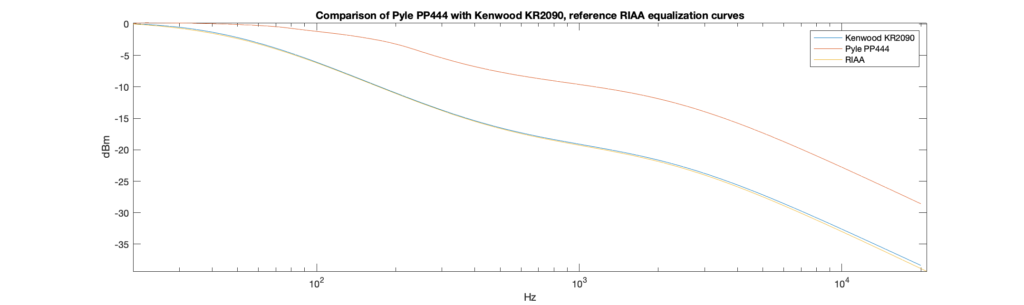
I decided to do a comparison. Using a 10mV input signal and a 20Hz to 20kHz log-spaced sweep, I generated the responses for both the Kenwood and the Pyle PP444 (seen below, compared to the reference RIAA equalization curve). I’ve normalized all three responses to 0dB at 20Hz to simplify comparison.
Sure enough, the Kenwood (blue line) perfectly follows the official RIAA curve (yellow line), while the Pyle (orange line) rolls off way more slowly. Even at 1kHz, the Pyle is about 12dB louder relative to 20Hz deep bass than it should be. No wonder things sound tinny!
I guess the summary is that I shouldn’t have expected much from a $13.20 (at press time) preamp, but nonetheless, I feel like I don’t have a good way to be sure if I’m getting one that actually delivers the response I want at any pricepoint.
I guess the summary is, if you care about sound quality, avoid the PP444. If you just want something that will ‘work’, I guess it’s fine.
Silent clip of the PVM in action. Youtube linked below.
Years and years ago, I heard about the AtariVideoMusic. A short lived music visualization device created by Atari in the late 70’s. It would hook up to your home hi-fi and living room TV and show off the music. Techmoan did a good introduction to it here, but imagine a very primitive version of MilkDrop.
Anyway, since before the time Techmoan did his review, I have been thinking about creating my own, modern-retro take on the idea. Music visualizers seem to have dropped off the face of the earth in the last few years, but I’ve always loved them.
Anyway, long story short, a couple of years ago I started making my own. I realized that the Raspberry Pi was the perfect tool for the job. It could easily do all the music visualization I wanted it to, and be built into the stereo component style box with an integrated, tiny, CRT that I envisioned at the time. Fate would have it that my old academic advisor had a tiny portable color television that he gave to me, gratis, and in the course of developing the code, I decided that the TV itself was perfect, so I just put the Raspberry Pi out of sight behind the TV and called it a day.
Video Tour
Software
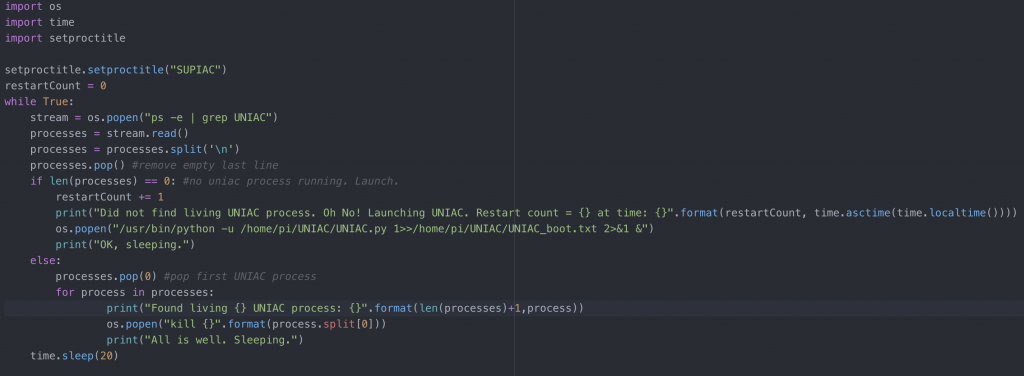
The software is all written in python, and can be found here.
There are two files, RaspberryVideoMusicSupervisor.py and RaspberryVideoMusic.py. The former simply makes sure the latter is running as a process. It allows me to automatically recover from the occasional crash and I have set up my Pi to simply launch that script on boot.
RaspberryVideoMusic.py is the main script. It relies on Pygame and Pyaudio. The basic loop is simple. Pyaudio captures audio frames and raises a flag when there’s new data.
There are some basic data ‘services’ available at all times, updated when new data is available. These include things like the audio frame, an FFT of the audio, and a detected signal envelope.
The main loop updates the Pygame display when new data is available. Every few seconds it randomly selects a different foreground and background visualization as well as randomly selected color schemes for each.
Hardware
The hardware is extremely simple. The display is a portable color CRT TV with a composite input. The audio input is a cheap USB sound card. The only trick is that the Raspberry Pi composite output tends to inject audible display noise into the audio. I fixed that by adding a USB isolator between the Pi and the USB sound card.
Additionally, because the sound card input is a mono mic input, it shorts the left and right channels together, creating a mono signal. That’s fine for the visualizer (it could pretty easily be hacked to handle stereo input), but it means that there should be a headphone amp between your signal source and the mic input to prevent the Pi from distorting your sound and making it mono.
Recently on the electronics subreddits, there was a series of posts by people showing off their collections of unique old display modules. I realized that I had quite a few sitting in boxes. Unlike a lot of the posts on Reddit, I am also able to power them on to show off the goods. Enjoy!
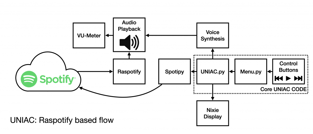
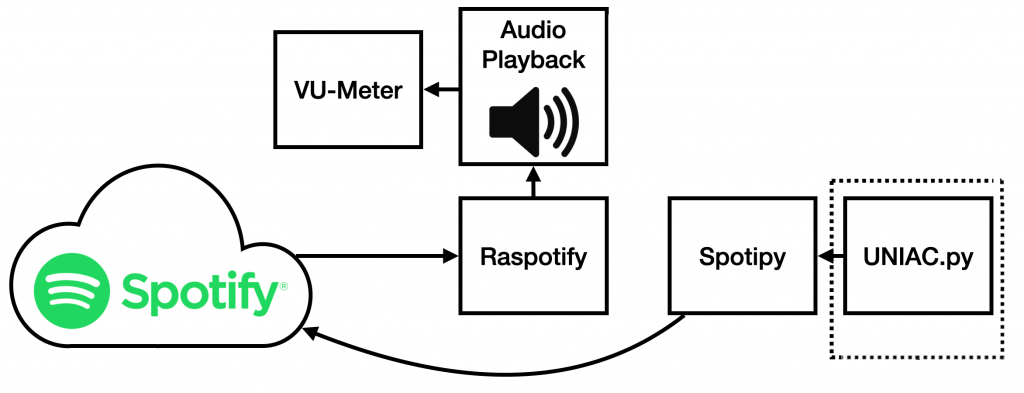
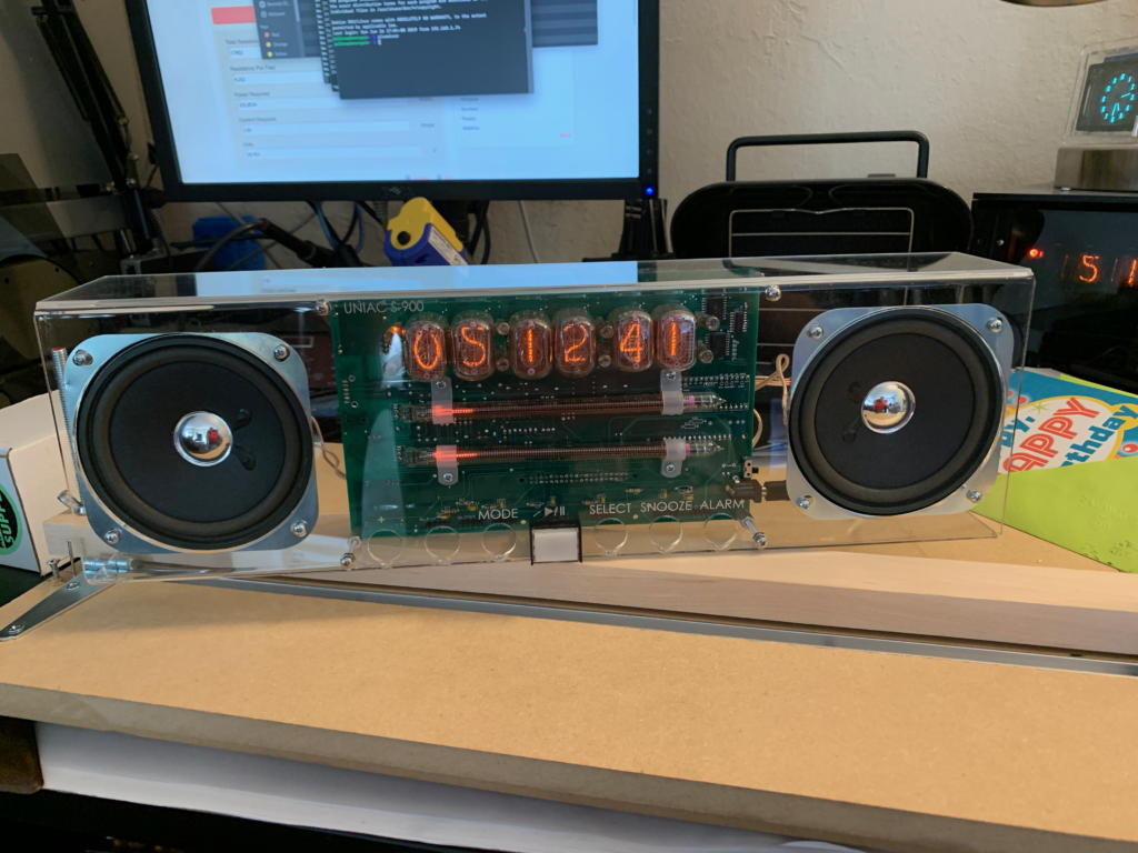
Most of you who see this post will have seen the original UNIAC post before this, and hopefully some will have seen the post detailing the hardware. For those who haven’t, UNIAC is a Raspberry Pi based Spotify playing boombox that is controlled with buttons on the front and displays status using Nixie tubes. This post will cover the software used to make UNIAC work — both tools developed by others and the software I wrote myself.
While I am writing this from the perspective of documenting UNIAC, the software could be pretty easily recycled to work with any display and buttons, you’d just have to rewrite the display and button event functions to support your hardware.
Also note that I did a major ripup of the UNIAC software after the original post, so this version does not use Mopidy, MPD, or Mopidy-Spotify. And if any of you have used those tools before, you’ll understand that’s a good thing.
I will start with a disclaimer however: I am an electrical engineer, not a software engineer, so this design will probably make software guys sick to their stomach. Sorry in advance…
Third Party Software
The first thing to understand about the architecture used in UNIAC is that control and playback of music are two separate processes. Raspotify is a software package that connects to Spotify and makes your RPi act as a Spotify endpoint. Essentially a dedicated speaker. There are a couple of similar packages that can give you a Spotify client on a RPi, but Raspotify has a trivial installation process:
curl -sL https://dtcooper.github.io/raspotify/install.sh | sh
The second part, Spotipy, is a Python library that you give permissions on your (paid) Spotify account. It allows you to see current playback status, and control playback on your Spotify devices (computers, speakers, etc). By combining these two, you can have a full Spotify instance running on your device with programmable control.
The two pieces are connected by the UNIAC Python script. UNIAC sets up a spotipy connection and then controls what device the playback occurs on. Since the name of the UNIAC Raspotify instance is constant, it simply has to tell Spotify to playback there, and music will play on the UNIAC hardware. This has the added benefit that I can ‘cast’ whatever I’m currently listening to over to UNIAC and it will just continue to play.
UNIAC / Spotify control.
The last piece worth mentioning is eSpeak, a relatively primitive speech synthesizer that takes strings from the command line and announces them. This lends UNIAC its characteristic robot voice when announcing settings information and playlist names.
Hardware Libraries
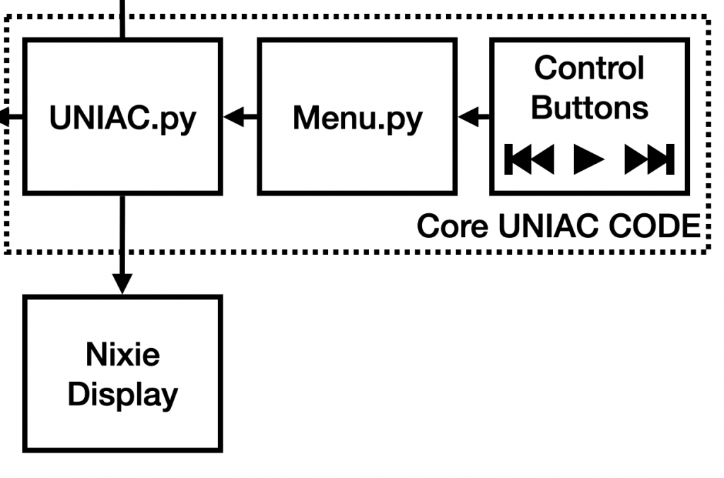
Path between the controls, the Display, and UNIAC.
The hardware interfaces are pretty straightforward, mostly. The buttons are controlled by an i2c GPIO expander, and Adafruit has the MCP230XX library to support it. For other GPIO, I use RPi.GPIO.
The last, and most unique library is the NixieDisplay library. It is a custom library that I developed to communicate with my Teensy 3.2 based multiplexing, crossfading Nixie display. In the first prototype, I used Taylor Edge SmartNixie modules instead of my custom display, so I also wrote a library supporting them on the RPi, though I’m not using it on the finished version.
These libraries are pretty straightforward. You print numbers to the tubes to display and forget about it.
The VU-Meter only has an audio input, so it doesn’t have any software control and doesn’t appear on any of these block diagrams.
UNIAC Software Architecture
The UNIAC software is essentially an interrupt driven button handler. There is a master ‘Menu’ class in Menu.py to which arbitrary ‘Modes’ are attached. An attached mode must provide a function handler for each physical button as well as a display update handler (and a few other helper functions).
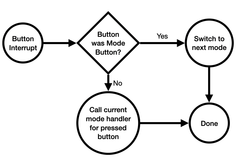
When a button is pressed, the Menu object calls the current Mode’s handler for that button.
Button Press Event
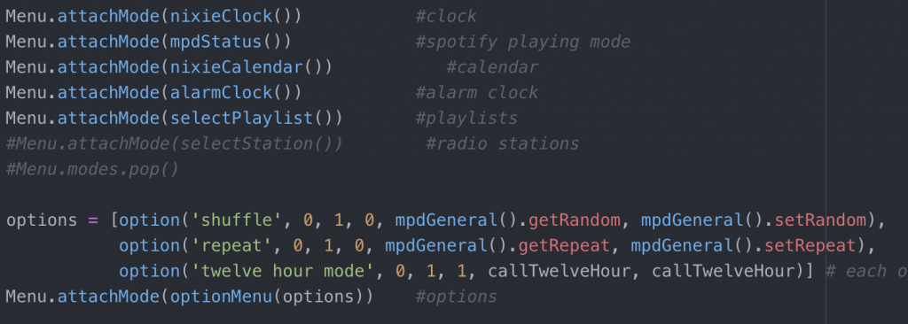
The UNIAC.py script creates a Menu instance and attaches the modes defined in that script. The modes (currently) are: clock, track time, date, alarm clock, change playlist, and options.
Modes attached to Menu in UNIAC.py
For instance, when the ‘Plus’ button is pressed in the track time mode, the menu object will use Spotipy to progress to the next track, but when ‘Plus’ is pressed in the alarm mode, it will advance the alarm time by one.
The ‘Mode’ button is a special case that does not call an attached handler function but instead changes the selected mode in the Menu object.
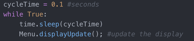
The Menu object also requires that each mode have a display update handler. This handler is called by the master UNIAC.py script in an infinte loop to update the display every 100 ms.
Display Updater
This code was actually based off of another (unfinished) project of mine which used two buttons and a character LCD. By changing the displayUpdate function and the button handlers, this script could be used for virtually any menu interface with multiple ‘pages’.
Interfacing with Spotipy
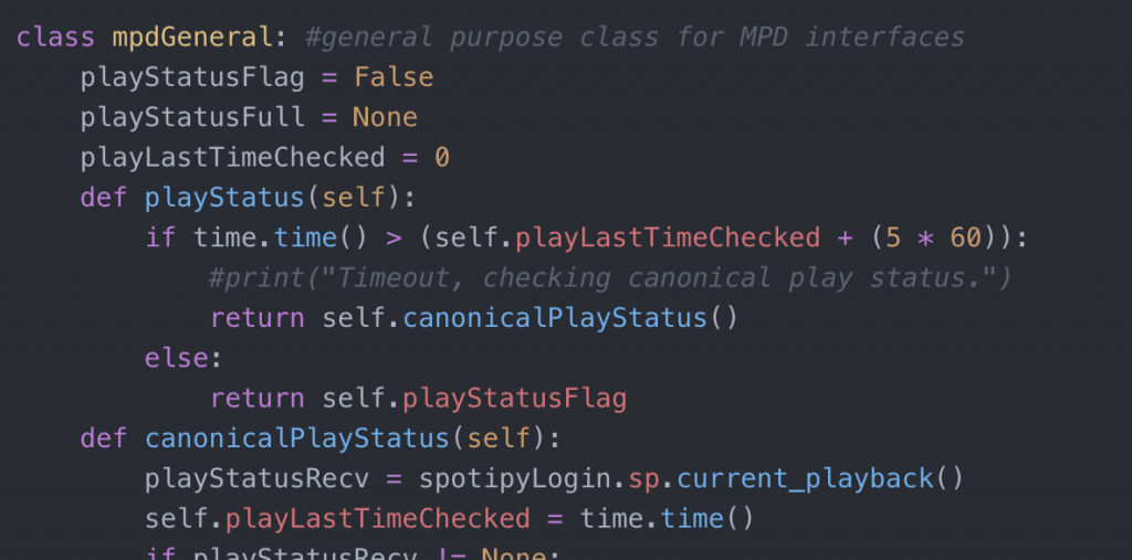
As discussed in the preceeding section, UNIAC is controlled through a series of button handlers. To interface with Spotipy, most of the modes used in UNIAC inherit from the mpdGeneral class.
mpdGeneral class definition
This class has a few static variables and references the globally available spotipyLogin.sp object, which is an instance of the bare Spotipy API created by the spotipyLogin.py script. It includes things like track status, play, pause, loading a defined playlist from URI, listing available playlists, et cetera.
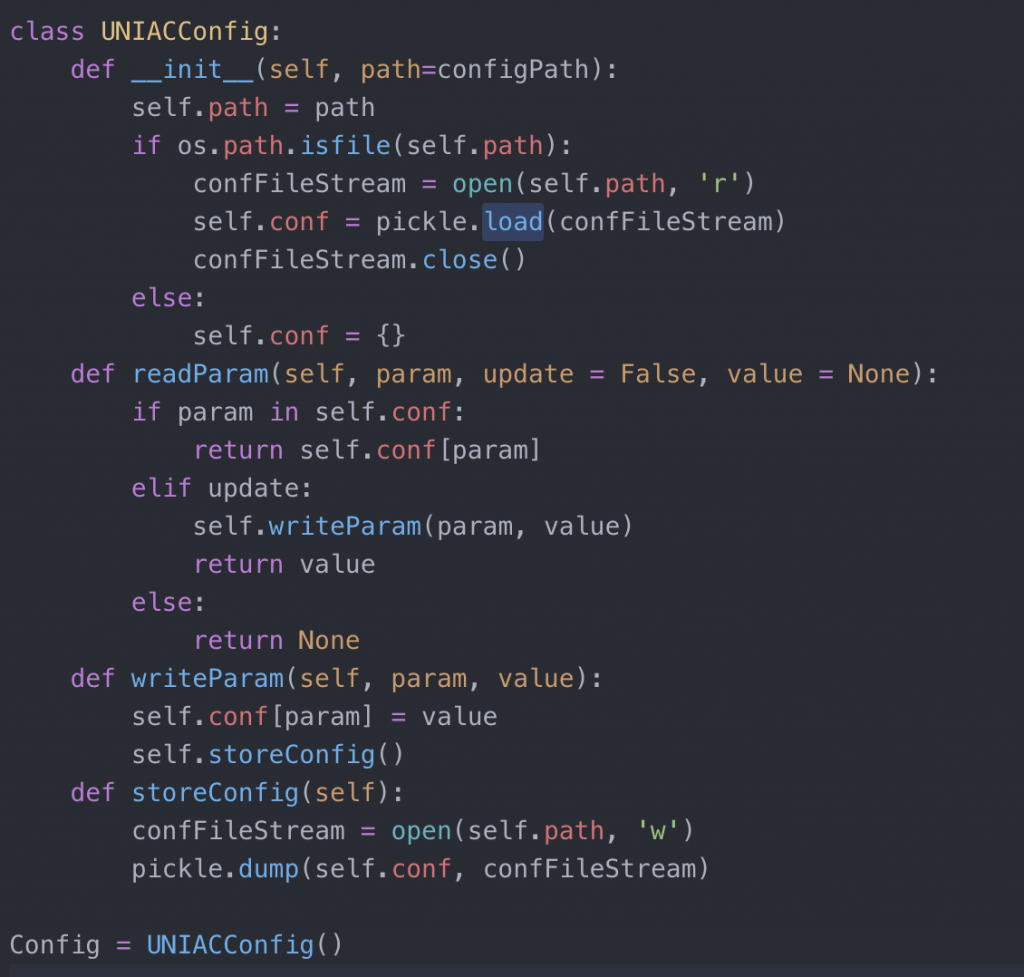
The UNIACConfig class allows settings like alarm time, current playlist, and settings to be pickled to a config file and loaded on restart. The other classes (including the option menu mode) use this class to handle i/o to the settings file, ‘UNIAC.conf’.
UNIACConfig class.
The remainder of the classes are more or less straightforward implementations of their self explanatory modes and hook the various parts and pieces together.
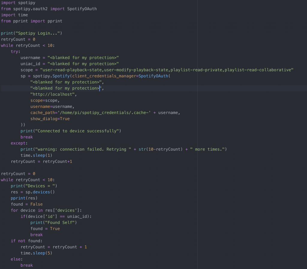
The last piece of secret sauce, which is not on git, because it is in m gitignore is spotipyLogin.py, a simple script which holds my Spotify login credentials and makes a logged in Spotipy object available.
The redacted version of spotipyLogin.py
UNIAC Supervisor
Finally, there is a UNIAC supervisor script. This is an independent Python process which checks if the UNIAC script is running and if not launches it. It also checks that only one instance of the script is running, and if a second copy has started somehow, kills all but the first process. It’s not strictly necessary, but is a nice-to-have feature. I ran without it for years, with only occasional failures.
UNIAC supervisor script.
Conclusion
The UNIAC software is a combination of several bits and pieces of code which allows a button driven paged menu system to control the Spotify web API and stream music for plaback locally on the RPi, as if it were a commercial product. The interface is ideally suited to a ‘Nixie Boombox’ but could be used with any oddball display you wanted with a little modification.
After sharing my last post on Reddit and Hackaday, I’ve gotten lots of kind feedback — and I deeply, deeply appreciate it all. More than anything else, it makes me regret not sharing this project with you sooner.
That said, the biggest ask has been for a detailed build guide. Unfortuantely, I didn’t document the build process in enough detail to write up a step by step guide, and I just don’t have the energy to build an entire new copy right now.
What I can do, however, is share discuss the design choices I made and share the build files. This post will focus on the hardware design of UNIAC, and I will follow it with a post detailing the software in greater detail.
Schematics
The schematic capture and layout was done in Eagle, and broken out into pages. It’s not perfect, by any means, but it’s clean enough.
Anyway, let’s go through the sections.
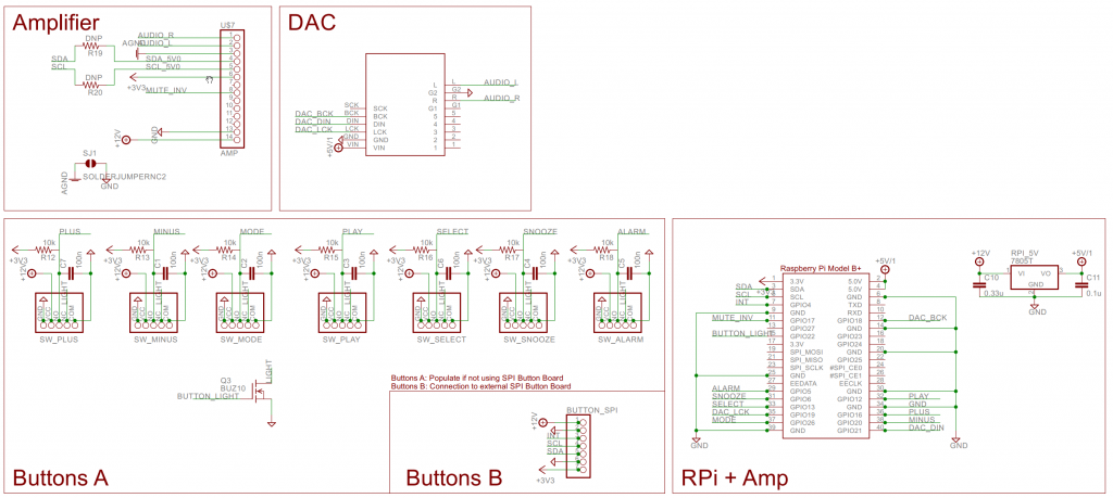
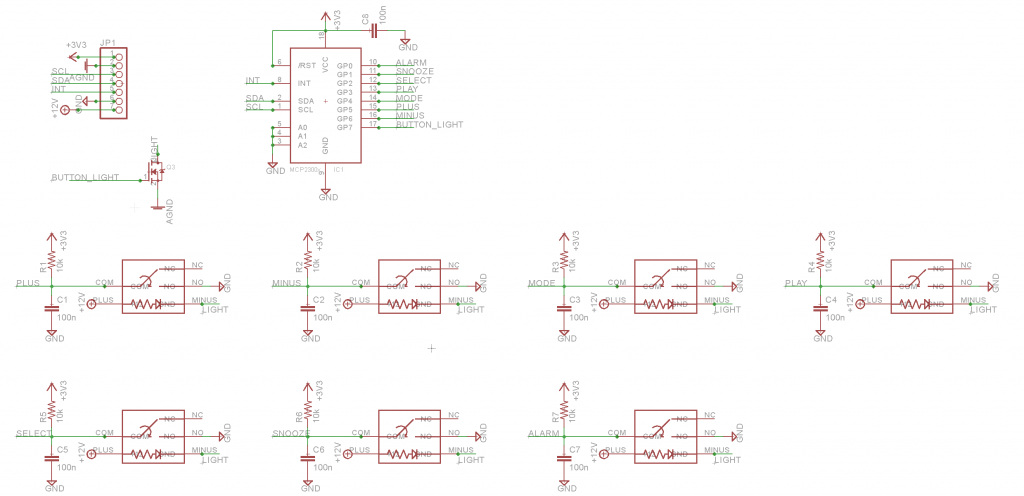
Raspberry Pi, Buttons, Sound Card, Amplifier
This section has:
The Raspberry Pi itself — note that the footprint says “Raspberry Pi Model B+”, but is actually sized for the Pi Zero W. I recycled an existing symbol because the header pinout is the same across both versions of the Pi, and simply forgot to rename it in Eagle. It also specifies a 7805 5V regulator to power the Pi off the input 12V bus. In practice I used a drop in switch mode replacement for the 7805 from Murata.
The button interfaces — supports two options to connect buttons. The first one, Buttons A, is for directly connecting to the motherboard. I used this option in the first two prototypes and decided to keep the option open here in case the button breakout board had problems, since I had the board space. The button connections here include a provision for +12V to illuminate the buttons, a shared switched ground line to control button illumination, resistors to pull up the buttons and caps for debounce.
Buttons B is a header for the button board, shown later. It breaks out the I2C bus connected to the RPI as well as a 3.3V rail for powering an offboard IC and a 12V rail for powering button illumination. Finally it has an interrupt pin so that the Pi can detect when the button board needs to be polled.
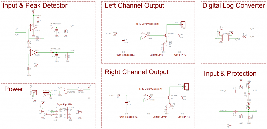
The next page of the schematic is a direct copy of my IN-13 VU Meter circuit. I won’t go into a full description of the theory, but it uses a quad rail to rail op-amp to save parts (I usually populate with an LMC660), and MPSA42 high voltage small signal transistors to drive the IN-13s. There is also an ATTINY85 micro running this code to make it act as a log converter. This saves parts and board area vs an analog implementation as well as allowing the VU meter to go to sleep if there’s been no audio for a couple of minutes.
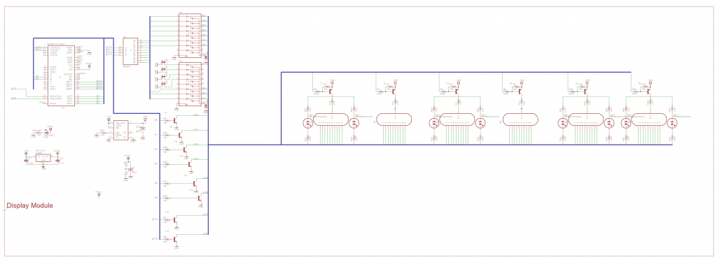
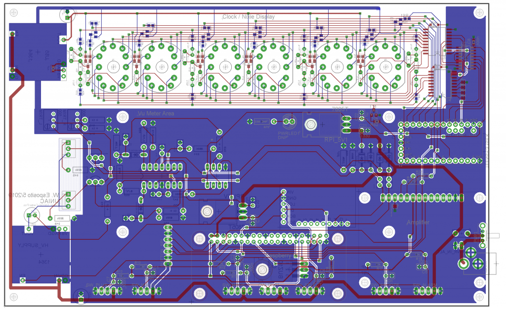
Nixie display section
The third page of the schematic covers the Nixie display. This design was inspired by Dave Jones’ (of EEVBlog) Nixie tube driver design, which attempts to save transistors by using multi transistor ICs. Ultimately, I’m not very happy with that part of the design as there seems to be enough leakage that minor ghosting is visible on the tubes. I’ll definitely revisit it for my next Nixie project.
The controller for the display is a Teensy 3.2 which accepts commands to display values on the Nixies and INS-1 neon lamps via I2C and supports crossfading between digits.
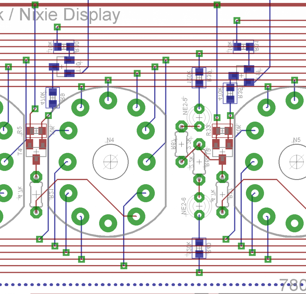
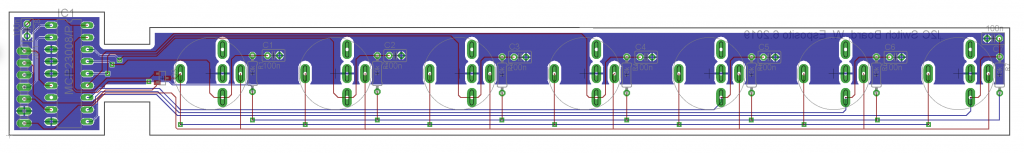
Button breakout board
Finally, The button board uses an I2C GPIO expander IC to provide the same functionality as the individual button headers shown earlier, but without having nearly as many wires. The downside is that it requires an extra IC to do the job, and once the buttons are in the case, they’re soldered to the PCB and are pretty much stuck for good.
Layouts
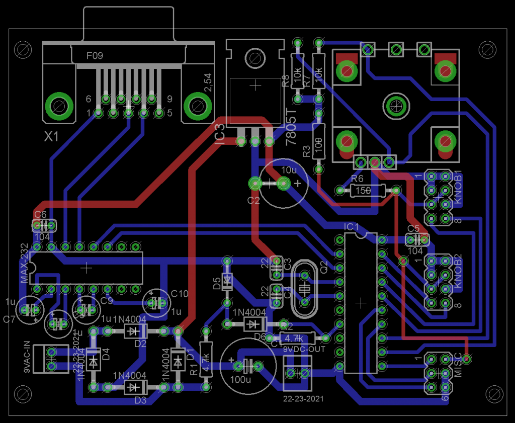
The UNIAC mainboard layout is pretty compact. There’s not too much to talk about. Most of the size was defined by the need to have the Nixies at the top, bargraph tubes in the middle, and buttons at the bottom. Except for the routing around the Nixies themselves, there were no space constrained areas. I did choose to put the Teensy and RPi near the edges, so that their USB ports were practically accessible, however.
UNIAC Mainboard.
I went to great lengths to calculate minimum creepage distances and trace widths, which I used as design rules to ensure the Nixie display would be safe while being as small as I could make it. When routing my HV traces, I assumed 200 V DC and used a calculator like this one. I ended up using approximately 16mil or 0.4mm as my minimum trace clearance.
Closeup of the HV nets for the Nixies.
For trace width, I used 4PCB’s calculator, and found that even 600 mA would only cause a 10˚C rise for a 6 mil (0.15 mm) wide trace, way more than any of my HV traces were going to carry.vI also chose to keep the ground plane far away from the HV areas for added safety. Given that the Nixies are multiplexed and connect to ground only at a few points, it made sense and decluttered the design.
Finally, we go to the ‘Button Board’. The front panel control buttons are mounted to the front of the case and then soldered to this PCB. It’s a fairly simple design, but it has a couple of notches to clear the standoffs that mount the mainboard and speakers to the case.
Button board.
The biggest pain about this board was getting it fabricated. The buttons have wide pins that need to be fabricated as small slots. This is because the pins are so wide and closely spaced that large enough circular holes actually overlap each other.
It took three tries to get the boards fabricated. I had to make sure that the slots were on the correct layer in the footprint and had to specifically reach out to the PCB vendor in advance to ask them to send checkplots to confirm that the board would get fabbed correctly.
The first order was from AllPCB without asking in advance and they simply milled the small circular holes instead of slots. The second time, they promised that they would send me checkplots, but just fabbed the board without doing so. They also ignored my customer complaint.
It was at that point that I switched to PCBWay, who provided checkplots as requested, but they actually had the slots correct on the first try, resulting in great boards. My only regret is that their matte black soldermask is slightly shinier than AllPCB’s so the boards don’t quite match the mainboard.
The bill of materials, that is, the list of all the components used, is fairly long. It lists all the components that go on the main board, as well as the button board, and all of the off board components that I could think of. Since it’s a big, ugly table, I’m just going to attach it as a csv. The major parts themselves are detailed in the first UNIAC post.
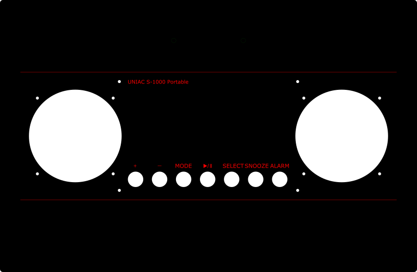
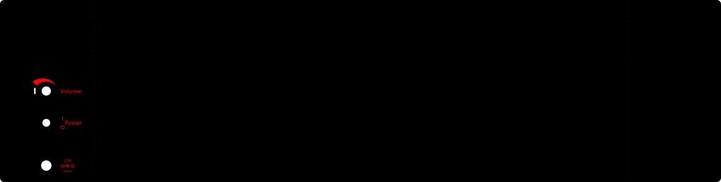
Making the enclosure was a blast. My workflow is terrible and costs me several pieces of plastic on each new design I come up with, to be honest. I design the acrylic pieces as 2D Inkscape images and handle the ‘3D Modeling’ in my head. It’s even lower rent than DaveCAD!
Front Panel. Bent along the red horizontal lines which are not visible in finished enclosure.Rear Panel. Bent along (Faint) dotted red vertical lines, which are not visible in the final enclosure.
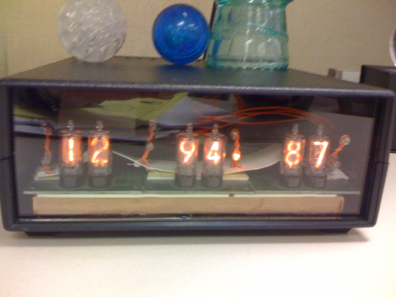
My fascination with Nixie tubes began around 2006. These beautiful retro tubes make amazing displays and have been made into hundreds of well documented clocks. At that time I bought a handful of tubes and got permission to build a Nixie clock as project for a senior level undergrad EE lab course. I actually built it as two separate boards, a serially addressed Nixie display and a serial output clock module.
Both the display and the clock were built around an AT89C4051 microcontroller, with direct drive using one K155ID1 per chip. The high voltage supply was a switch mode module from LEDSales (I have since moved on and all my more recent projects use the Taylor Edge 1364). The tubes themselves were Burroughs B5750s, which I got on pre-made break out cards with edge connectors, two tubes to a card.
The clock module also used an AT89C4051. The very simple timekeeping circuit took an AC input through a voltage divider and zener clamp and counted pulses. This is actually a surprisingly stable way of keeping time, as at least in the US, electric utilities will actually slow down or speed up frequency slightly overnight to make up for irregularities during the day. This means that while line frequency clocks are worse than cheap quartz clocks hour to hour, they are actually generally more accurate month-to-month.
Clock PCB Schematic
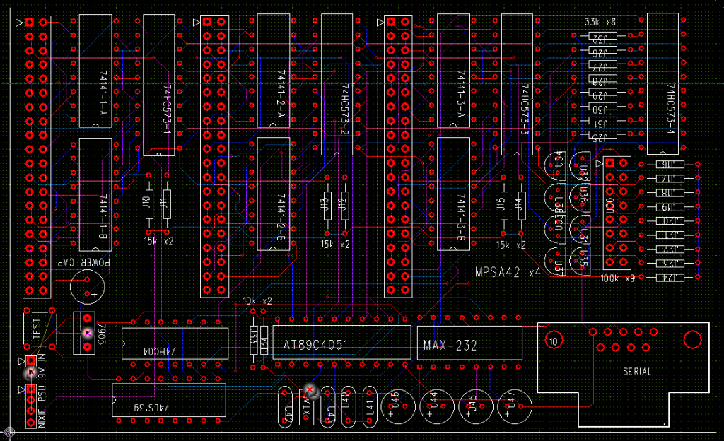
For the display board, I didn’t have a saved copy of the routed PCB, and as it was one of the first boards I ever laid out, it wouldn’t have been good anyway, so I just re-downloaded PCB123 (again, I was a ‘young player’ as Dave Jones would say) and ran the autorouter to give you the just of the board. Each 40-pin header drove a dual Nixie card (god, the inefficiency!)
Nixie display board, takes serial input via DB-9 and displays the data on six nixies and 8 NE2 neons.
I was never really happy with the clock design, from a user perspective, so it got put away pretty quickly. The display module, on the other hand was really satisfying. It ended up at my first full time job. Because I worked at the local power company, and had access to real-time SCADA data for the grid, it was used to display the power consumption of the city we were in (in MW).
My first ever Nixie display, showing 1294.87 MW of power consumption.
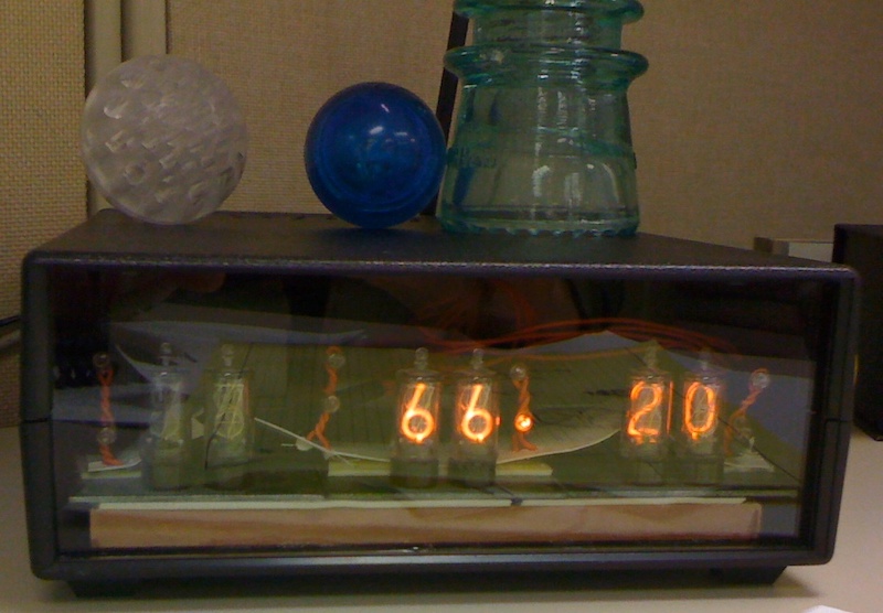
The code ran in Python and used a command line utility to extract the various datapoints, which it then drove to the display, updating every five seconds or so. The final version would rotate between showing power consumption for two cities that we served, and the temperature (˚F) in each of those places.
Temperature in degrees Farenheit.
It definitely got a few looks over the years that I had it running, and I still have the display in a box somewhere, but I’ve moved on career wise, so I don’t have the cool data to display in real time anymore.
Oh well, not much of a story, but I thought I might as well document it and share.
As promised, here is a verified (I have used this and successfully assembled the boards) footprint / part for the PCM5102A I2S sound cards that can be found on amazon.
I feel like almost everyone who has had to deal with
anything outside the most mundane audio setup on Linux machines has experienced
the pain I’m about to describe. On Mac and Windows machines, audio seems to
‘just work’ (TM) (R) (C) — and on linux desktops like Ubuntu it seems to be
fine too.
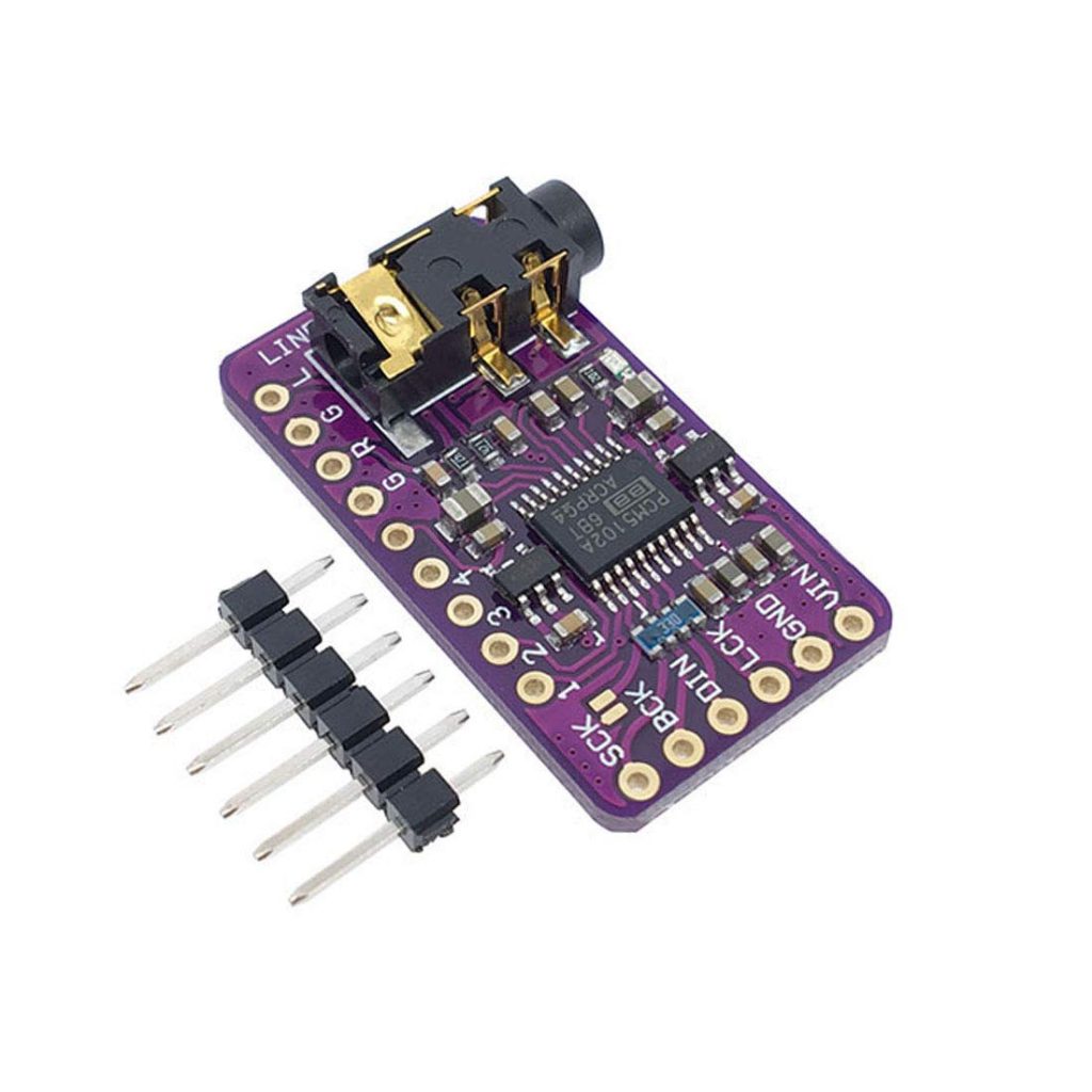
PCM5102A Module, product photo from Amazon.com
For my UNIAC project however, I went a little off the rails (dun-dun-dun). UNIAC 2.0 uses a Raspberry PI Zero W, which doesn’t come with any onboard analog audio output, forcing me to use a third party sound card. Since the project had a nice backplane motherboard, I wanted a module I could just plop down on the board as if it were a component. Ultimately, I settled on a PCM5102A module like this one, which took audio as I2S samples and cost all of $8. For the final, working version of this, I used Raspbian Buster (July 2019).
As an aside, I created an EAGLE Footprint for the module, so you can incorporate one into your own projects if so desired.
The Solution
To get it all working, we need the OS to do four things:
Recognize the new I2S sound card.
Use it by default.
Provide some software volume control.
Mix multiple audio streams at once
PCM5102A Drivers
These no-name PCM5102A modules are sketchy at best, and come with no meaningful support and no manual. Fortunately, they use the same IC as the Hifiberry DAC+ project. After getting this thing going I feel somewhat bad for not buying their board, but the form factor is just not what I need.
In theory you can follow the Hifiberry DAC+ setup instructions to get basic output going – but don’t use them if you want software volume control. For me following those instructions resulted in a weird situation where the software volume control didn’t actually stick after reboot, so I recommend staying away.
Volume Control
What did work for me, was a modified version of these instructions. To get basic volume control working, I used the first few steps of those instructions. I’ll duplicate them here in case the site goes down.
Software setup
First we need to disable the onboard sound by editing alsa-blacklist.conf:
sudo nano /etc/modprobe.d/alsa-blacklist.conf
Add:
blacklist snd_bcm2835
Save and exit (^X, Y, enter).
Now, to set the IO, edit config.txt:
sudo nano /boot/config.txt
Add:
dtoverlay=hifiberry-dac
Remove or comment (#) the line:
dtparam=audio=on
Leave the line:
dtparam=i2s=on
commented out.
Save and exit (^X, Y, enter).
Next add some alsa (sound) configuration:
sudo nano /etc/asound.conf
Paste the text below:
pcm.!default {
  type hw
  card 0
}
ctl.!default {
  type hw
  card 0
}
If you have an amplifier you can connect via a phono lead you can now test it via: speaker-test -D -c -twav So:
speaker-test -D default -c 2 -twav
This is a continuous test saying ‘front left’ and ‘front right’ alternately from the appropriate speakers. Enter ^C to stop.
Adding Software Volume Control
This is an optional step that adds a software volume control into the sound processing sequence.
sudo nano /etc/asound.conf
add the following:
pcm.sftvol {
   type softvol
   slave.pcm "plughw:0"
   control {
     name "PCM"
     card 0
   }
Enter or change the pcm.!default section to:
pcm.!default {
   type plug
   slave.pcm "sftvol"
 }
Save and exit (^X, Y, enter).
Now we can test it, as before:
speaker-test -D default -c 2 -twav
This should give alternating “front right” and “front left” from the respective speakers.
Great, but what about multiple streams?
Here’s where we go off the rails. We need to add a software mixer to this cozy little ALSA setup. Fortunately, DMIX is a thing. There are a few dmix examples out there. What we need to do, however, is connect dmix to softvol to a PCM sound device. This I could not find documented clearly anywhere on the internet, so here we are.
pcm.!default {
  type plug
  slave.pcm "softvol"
}

pcm.softvol {
  type softvol
  slave {
    pcm "dmix" #redirect the output to dmix
  }
  control {
    name "PCM" #override PCM slider to set softvol lvl globally
    card 0
  }
}
Great, Now What?
To get MOPIDY to work (my ultimate goal here), I had to do two things:
Install mopidy-alsamixer.
Edit ~/.config/mopidy/mopidy.conf
In mopidy.conf, I had to change the audio section to this:
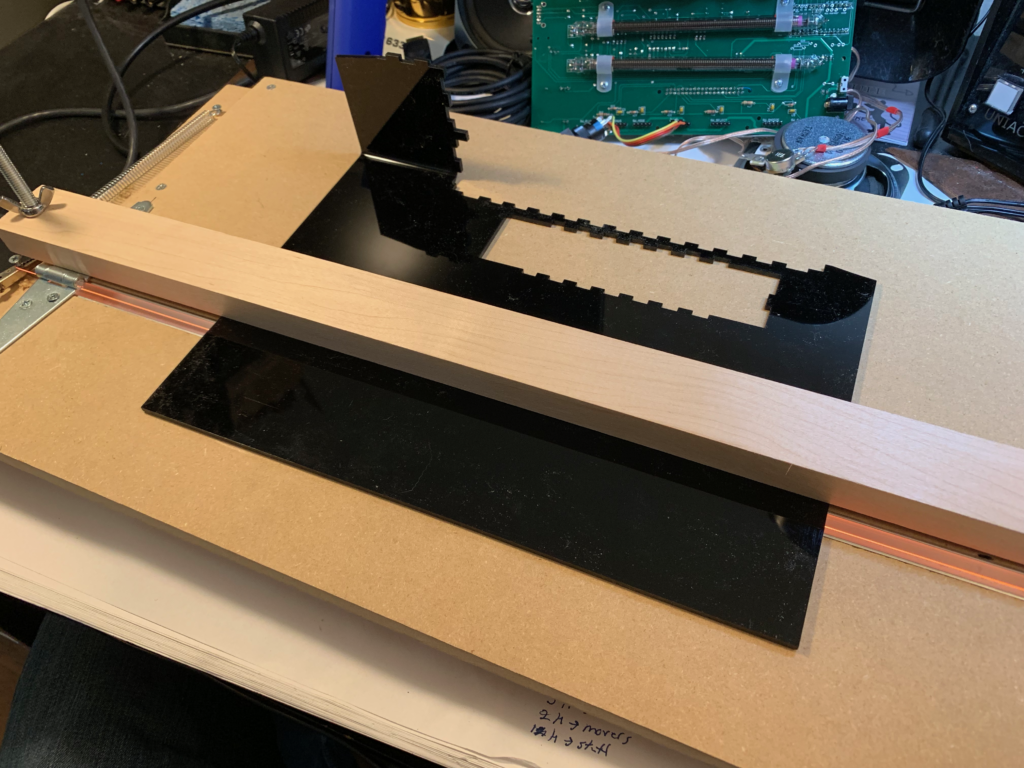
A few months ago, I was thinking about the best way to build enclosures for my projects. My go-to has been the ‘acrylic sandwich’ method, where I laser cut a handful of pieces of acrylic and bolt them to my PCB with standoffs.
An example of one of my acrylic sandwiches.
This looks reasonably good. More professional than hand built project enclosures, and less cookie-cutter than using a standard project box. But it has its drawbacks and limitations. You can cut slots in the front and back of your project and then use the tension in the standoffs to hold side panels in place, but these slots have to have a fair bit of slop in them as the thickness of acrylic sheets varies fairly significantly from manufacturer to manufacturer and even seems to vary lot to lot from cheap vendors.
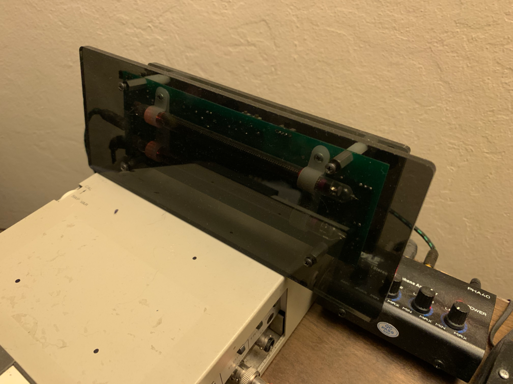
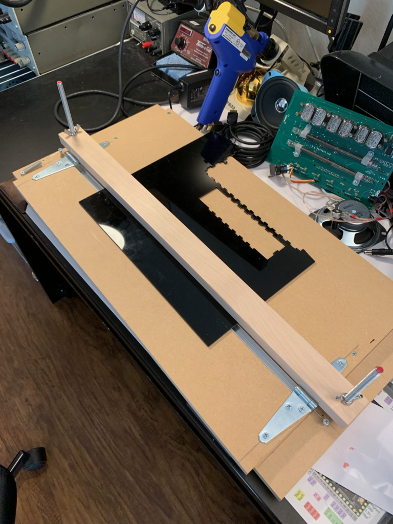
To deal with this, I decided to build an acrylic bender. Basically, acrylic has a very low melting point, so a beefy benchtop power supply can heat up nichrome wire, enough to bend it. Nichrome wire is the same stuff that cooks your toast in the morning, and it can be had rather cheaply off of Amazon. To build an acrylic bender, basically all you need to add to the two aforementioned components is some bits and bobs from home depot. In my case, I got one 24″ x 24″ sheet which I got cut three times to form a base, a working area and a hinge area. You add a small amount of U-channel under the hinges, and voilá, you have a bender.
Acrylic bender, hot and ready with a sheet of scrap acrylic for testing.
With one afternoon of building, I had myself a jig that was trivial to use and cost less than $50 total, way less than what you’d pay for a professionally made device online.
Slightly wider view of the acrylic bender.
With that I set about making the enclosure I had in mind:
With just a few minutes work.
The angles are pretty easy to make, and I don’t have a protractor to get exact angles (definitely a future improvement)! With my 35V 5A benchtop supply, it only takes about five minutes to get the acrylic hot enough to bend easily, and then you have to hold it in position for three or so additional minutes while it cools off.
One note, which you can see in the above picture, is the danger of having holes or edges in your acrylic close to the bend line. The hole edges themselves softened and deformed with the bend. In a later revision of the enclousure, I backed off the holes by ~1/2″ and saw no deformation, so it’s not a major drawback.
Now, with two bent pieces of acrylic, I can make a neat clamshell enclosure that is sturdy and looks professional. Definitely worth the investment.
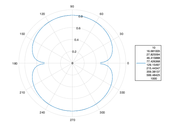
For a while, I’ve been thinking about noise cancelling microphones. I realized the other day that in order to ever hope to build one, I needed to model it first. What I ended up doing was building a model in matlab (of course), which includes the following simple classes:
A waveform class to allow for quick generation of sine waves.
A wavesource class to allow positioning of those waveforms in space.
A microphone class to generate wave recievers positioned in space, which computes the distance between itself and the source in order to phase shift the incoming wave.
Then, to get waveforms, you can take the output audio from multiple microphones (which is effectively time aligned) and do math with it.
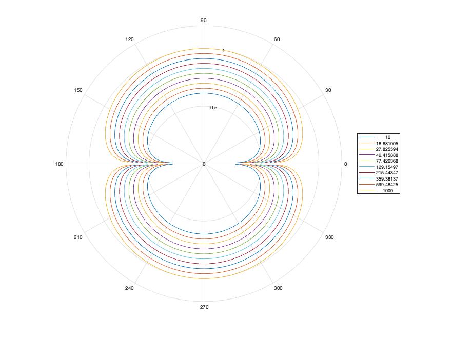
Then, by sweeping the wave sources through space, we can plot the pickup patterns of different wave forms.
By sweeping the frequency of the waveform over successive sweeps, we can see that impact as well.


