Episode III: The Investigation continues.
Thinking on the matter, I suddenly considered the possibility that the tubes were wired backwards – that is, pins 1 and 3 were reversed. The thing is, I was sure I had tested it when I was in the breadboarding phase of the project — there were no markings on the tubes, but I found that if I connected them the other way, the neon glow did not attach to the bottom of the tube, resulting in a floating, glowing bar in the middle of the tube, instead of a nice controlled bargraph.


Figure 1: A tube with a floating glow (top) as opposed to a normally functioning tube (bottom).
Connecting them the way I had caused the tubes to strike and stick to the bottom of the tube and march upward reliably. This had to mean that the tubes were wired correctly, right? The fact that I was driving them with 10mA instead of 5 was probably just an artifact of their age.
… or so I reasoned at the time.
Facing dying tubes, I decided to re-evaluate that conclusion. Reviewing the IN-13 datasheet, I noticed that it did indicate a “pin one” mark, even if I had been unable to find it. Looking at my tubes closely, I found a tiny daub of paint that might be a “pin one” indicator, as seen in figure 2. And if it was, it meant my tubes were backwards.
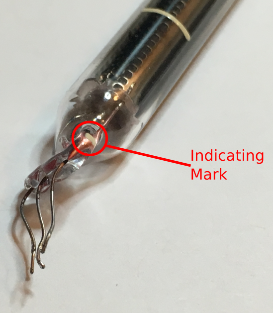
Figure 2: Indicating mark.
I desoldered my tubes and flipped pins 1 and 3, careful to keep a clearance between the awkwardly bent leads, as in figure 3. Powering the tubes on, I again saw a “floating” glow on one of the two tubes, but the other one stuck. Frustrated, I power cycled the tubes. Voila! Both tubes stuck and held. Power cycling them again, I found that every time thereafter, the tubes held correctly (even a few weeks down the road, I’ve only seen the floating glow one more time on power up, and it “snapped” back of its own volition after a few seconds).
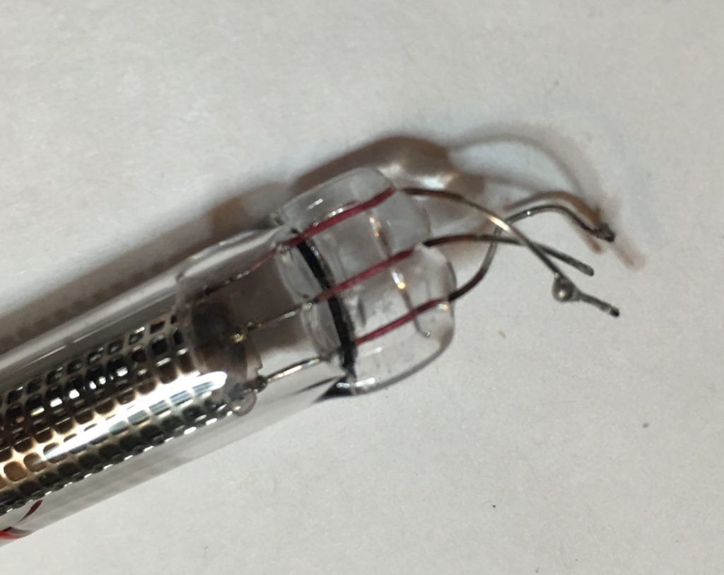
Figure 3: Bent leads on flipped tubes.
What’s more, the tubes hit full scale very easily! Measuring, I found that 5mA was enough to drive them to full scale. What’s more, I found that the tubes had less “inertia” – that is, they seemed to change length more quickly and snappily.
The lesson: Believe the datasheet, and if something is out of spec, believe that it’s out of spec, even if it seems to “work”.
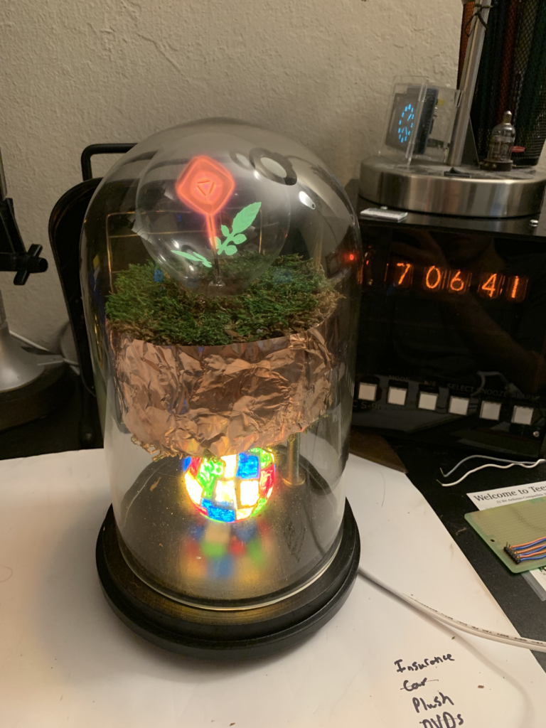
Also of note, on correctly connecting the tubes, the “auxiliary” cathode will glow on its own, something that is not seen when the tubes are connected backwards. Figure 4 shows the extra “bump” at the base of the tube when lit correctly. If you see no bump on your IN-13, you’ve got it backwards!
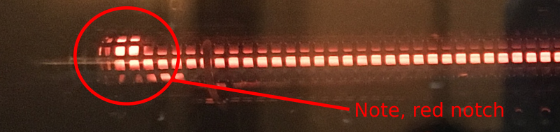
Figure 4: Secondary cathode properly illuminated. There is no visible notch if the connection is reversed.
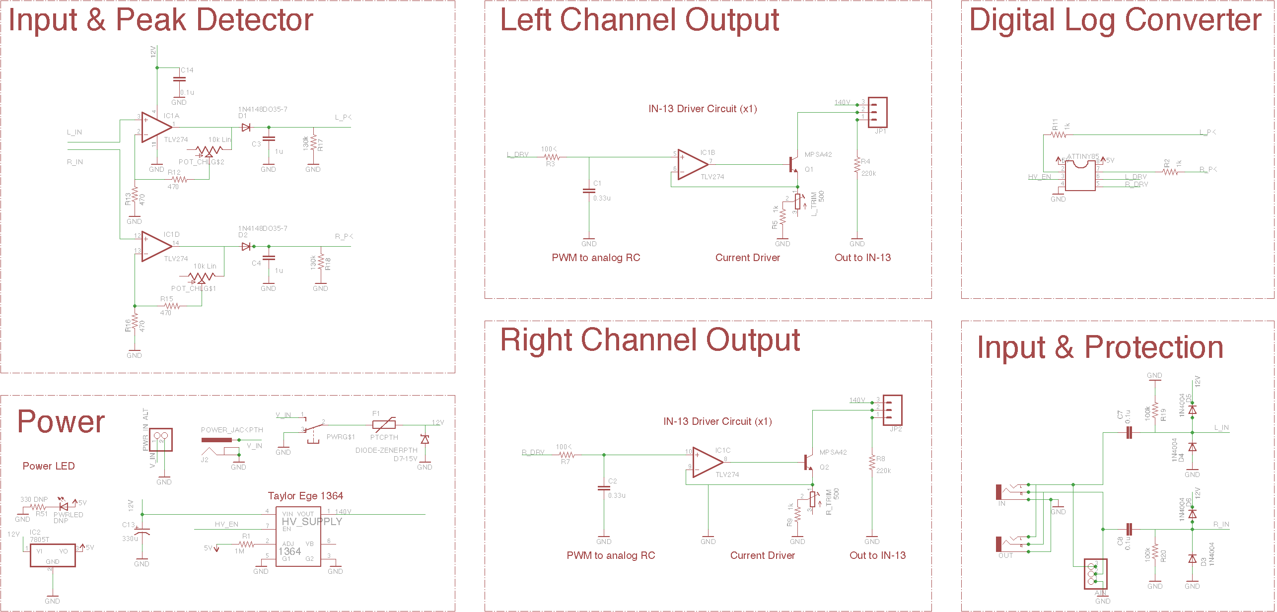
One more post to go, where I outline the changes to the schematic, and share a final revised version.