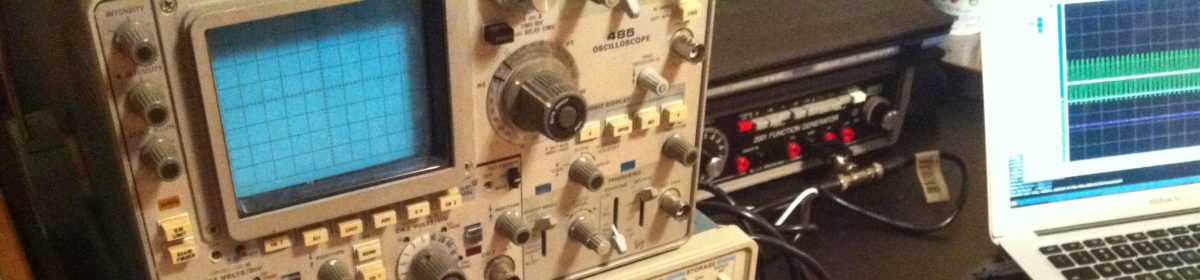
After all that work, I found that the lower “inerita” of the correctly connected tubes meant that the display itself had a twitchy response — the fix was simple, increase the capacitance at the VU-Meter node. I simply replaced the 0.1uF ceramic caps at the peak detector stage with 1uF electrolytic. Since this is a single rail design, that shouldn’t be a problem.
Additionally, since the tubes need 5mA instead of 10+ to go full scale, I replaced the 220Ω control current limiting resistors with 1kΩ resistors — the trim pots now sit most of the way to 0Ω instead of most of the way to 500Ω as well.
The final change was going back to a 10kΩ linear taper potentiometer, instead of a 50kΩ log taper part. This was done because I found that the 50kΩ part was simply too sensitive. On normal signals I’d encounter in real life, the pot stayed turned way down anyway. I had used 10kΩ on the prototype and it just worked better.
So, with all that in mind, here’s what the final schematic turned out to be:
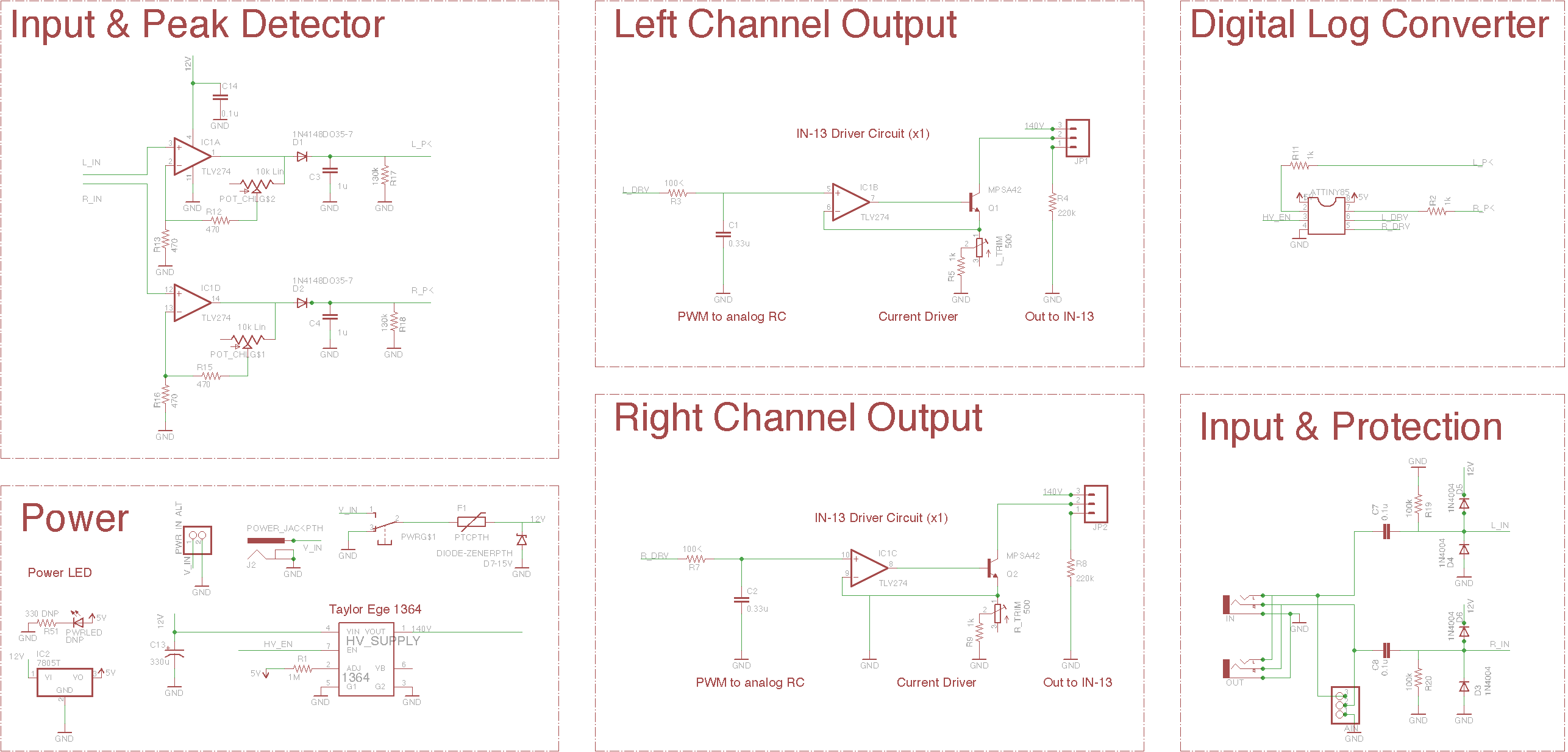 Figure 1: Final schematic.
I like this one so much, I may put up a Tindie account and try to sell the stock of the modules that I have parts for. We’ll see if there’s any demand. It’d be kinda neat to have someone actually buy a part that I’ve designed.