About a month ago, I was watching TV. As usual my IN-13 VU-Meter was dutifully bouncing away with the dialog.
Out of nowhere, one of the tubes made a “tink” sound and the current control went away — the tube stayed ignited, but the “bar” was stuck at the bottom.
I noticed that the spacer at the far end of the tube was swinging freely, unlike the other, functional tube. Clearly, something had failed — it appeared that the IN-13’s control cathode had eroded and snapped. Chalking it up to a one-off failure, I dug into my spare nixie box and swapped out the tube.
About a week later, the second tube exhibited exactly the same behavior! This was not a one off, but an early failure mode of the tubes. While a year and a half of use seems almost acceptable, I had expected much more life out of these tubes. Suffice it to say, the game was afoot.
My first stop was the best Nixie forum on the internet, Neonixie-l. Given the circuit schematic and my description, they were as baffled as I was – these tubes generally last much longer than I had experienced.
Doing a little analysis of my circuit, the conclusion was that the most current my circuit could drive through the tubes was 10mA, which matched my own measurements. Unfortunately, the datasheet translated by tubehobby indicated that the maximum current through the tubes should be about 5mA. More current would shorten the lifespan of thetubes non-linearly, so some investigation was warranted.
To the bench!
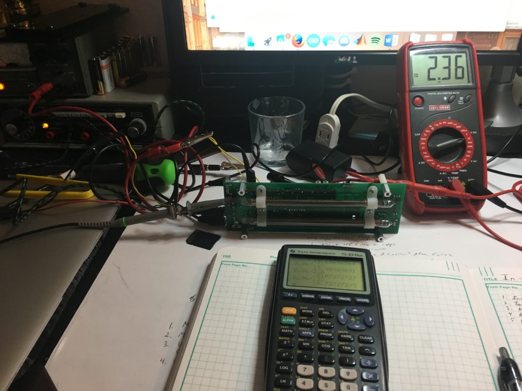
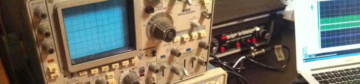
Figure 1: The setup. Multimeter, Function gen, DC power supply. Not pictured, scope, second function generator with AM input.
Investigation steps:
1. Scope HV line (HV supply is TES 1364 module)
2. Multimeter on 220Ω shunt resistor to get I_control
3. Input AC Signal — steady 10kHz, varous levels
4. Input AC Modulation signal — 10kHz AM’d 100% depth, 1Hz
5. DC Signal Input — remove Microcontroller and input DC to 100kΩ resistor LPF before the voltage follower.
Results:
1. HV Line, no input signal: Mean = 143V, V_pp = 8V
2. HV Line, full scale input signal (1.8V PP 10kHz sine wave — to front end): Mean = 143V, Vpp = 9V
3. Measure control current full system, using AC signal input:
I_shunt, no signal = 1mA (micro is still here, did not scope micro, but I suspect it was putting out a small nonzero PWM value)
I_shunt, full scale = 11.5mA
4. Measure control current, DC injection to IN-13 driver:
| Vin (V) | I_shunt (mA) | Col. Length (cm) |
|---|---|---|
| 6 | 13.9 | 11 |
| 5 | 11.4 | 11 |
| 4.5 | 10.9 | 11 |
| 4 | 9.4 | 10 |
| 2 | 4.9 | 5 |
| 1 | 2.41 | 2.5 |
| 0 | 0.045 | 0.5 |
I also measured the current through the cathode resistor (220k in series with the non-control cathode to ground):
| Vin (V) | I_cath (mA) |
|---|---|
| 0 | 0.04 |
| 0.5 | 0.26 |
| 2 | 0.38 |
| 4.5 | 0.5 |
Under normal operation, the tubes will never see more than ~11mA, which is substantially higher than the 5mA expected max current to get the full scale, and these tubes have seen a many of hours of burn in.
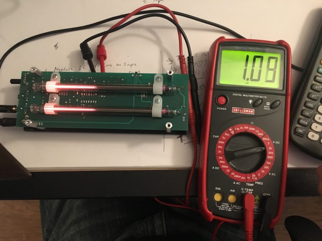
Figure 2: 5mA, should produce full scale.
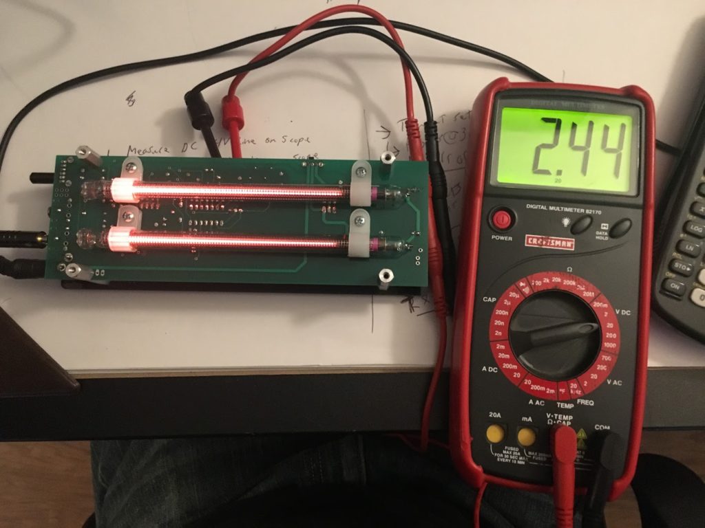
Figure 3: 10mA, actually produced full scale.
Also noteworthy here was that the striking voltage is above the max. Taking a closer look at voltages, the voltage between the anode and the indicating cathode when the tube is at 0 scale is 111V. When I drive it to full scale, it rises to 139V. Reading the aforementioned datasheet correctly, the 0 scale drop across the anode to indicating cathode should be at max 99V – it was out of spec but not grossly so.
The only thing I could think to do is adjust the HVPS to be drive them at a lower voltage (120V), but my recollection from when I breadboarded this was that they did not strike reliably below about 140V.
Stay tuned for the realization, the follow up and the fix!