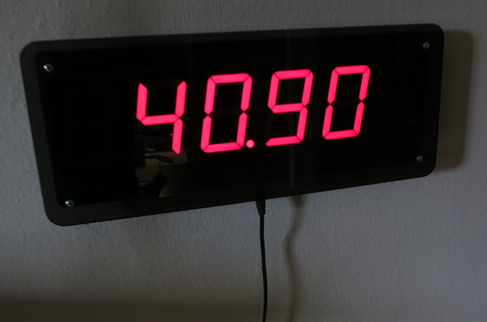
Note: This post is based on a word document I wrote and archived back when I finished this project in April of 2014.
Background
The Sidereal Clock is a simple thing. It tells you exactly how much daylight you have left. Once the sun sets, it goes negative and tells you how much nighttime remains. I realize it’s a misnomer, ‘sidereal time’ (http://en.wikipedia.org/wiki/Sidereal_time) would really describe a clock based around the movement of the fixed stars, but ‘daylight clock’ is a rather ambiguous and forgettable name.
The Sidereal Clock started from an idea. Well, someone else’s idea. My academic advisor saw a clock at an art installation (supposedly by James Campbell – http://www.jimcampbell.tv/portfolio/objects/untitled_for_the_sun/, although I haven’t seen it with my own eyes) that measured the percent of daylight remaining using a photo detector to determine when the last sunrise and sunset were. My advisor thought this was a really novel way of showing time, and I agreed. The implementation, however elegant, is rather impractical. It requires some reliable uninterrupted access to outdoor light, which suggests a ruggedized installation of a photo detector outdoors with a line leading inside to the display unit. Certainly impractical for many people, but really cool nonetheless.
Generation 1: Wired
My advisor, had an upcoming freshman class and some old 2.4” seven segment displays scrapped from a bowling alley. He’d suggested a clock that would provide the same information, but which would show his freshman the cool stuff you could do with an Arduino. This meant the following requirements:
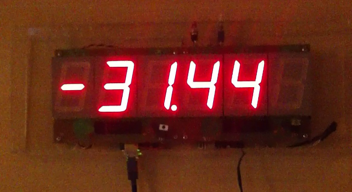
- Automatic network time setting.
- Those bright displays, each with three 2.4” digits.
- A way to calculate sunrise and sunset.
What I came up with wasn’t much of a leap. I basically ganged together the displays, which were on boards with handy shift registers, grabbed and Ethernet Shield, and off I went!
I could of course get the time from NTP servers (there’s even an example that comes with the Ethernet Shield), and I found that the Navy offers a web page that would calculate the Sunrise and Sunset time for me. It’s actually pretty neat! All I had to do was scrape it for that data (check it out http://aa.usno.navy.mil/cgi-bin/aa_pap.pl). I wrote a tiny PHP script which I hosted on my own domain to act as an intermediary and then had my Arduino parse the text output and use it to set my clock. Bam!
I laser cut a relatively crude acrylic case in our campus shop and brought it to show the students. Overall, a decent outcome for a few evenings work, if I do say so myself.
Generation 2: Wireless
Unfortunately, my advisor didn’t particularly like the fact that it required an Ethernet cable (neither did I, to be honest), but I let it sit for a season, because it was providing good service on his wall and occasionally inspiring students. After about six months, the glue holding the front of the hastily assembled acrylic case gave out. I decided to use that as an excuse to improve the design. I managed to get a hold of the then brand new Adafruit CC3000 breakout (https://www.adafruit.com/products/1469) and see if it would do the trick for NTP. It worked like a charm (that CC3000 chip is really cool in my opinion, although I must disclaim having been a TI intern in the past – but not involved with the CC3000). The next trick was to free myself from web page parsing. After some more web spelunking, I found someone who had solved exactly this problem in C, and all that was required was to port it to my Arduino sketch. That original code can be found here (http://souptonuts.sourceforge.net/code/sunrise.c.html).
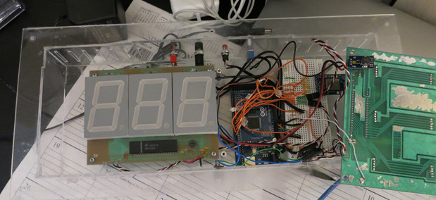
Finally, I added a real time clock module based on the DS1307, which allowed me to virtually never synchronize with the internet. At this point, I modified the firmware so that it would only check NTP when the user
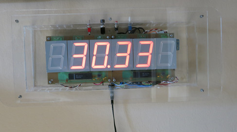
pressed a button on the top of the clock. The downside to all this was that the addition of the CC3000 libraries, combined with the DS1307, various time libraries, and lots of text in the serial interface used for setting parameters (like GPS coordinates) meant that there simply wasn’t enough program memory (EEPROM) on the 32k of an Arduino Uno, and I had to switch to a Mega2560. Still, all in all, a successful result, even if it is rather ugly on the inside.
I dutifully returned my Wi-Fi friendly clock to my advisor and it found a home on his wall, once again occasionally coming down to show students just how much cool stuff you could pack onto a measly Arduino.
Generation 3: Single Board
Thinking I was done with the project I nearly moved on, but the cool factor of the design kept bugging me. I wanted one for my own wall. After some searching, I actually found that Jameco (our beloved local bay-area parts supplier) carried the exact same, beautiful 2.4” tall seven segment LEDs (http://www.jameco.com/webapp/wcs/stores/servlet/Product_10001_10001_97199_-1) this opened the possibility of building a single board version of the clock. I started down the road of a full replication of my previous effort, including an integrated Mega2560, CC3000 and RTC. After getting said board half laid out, I came to a realization…wireless is a luxury, and I have no need for it in a design for me. Stripping out the wireless removed a lot of fat from the code. I could pull most of the serial interface as I didn’t need to set things like SSID and password, I could pull several large libraries, etc. It made it trivial to fall back to an Atmega328P (of Arduino Uno fame) as opposed to the more complex and expensive surface mount microcontroller used in the Mega2560.
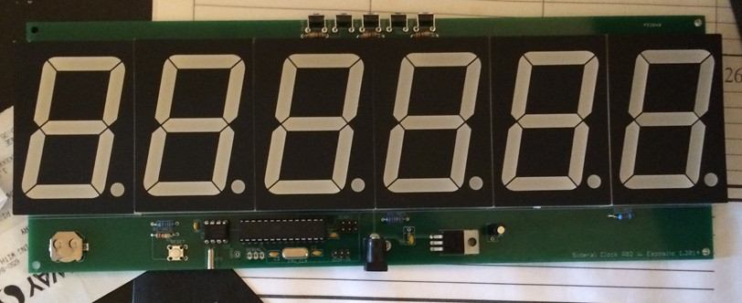
The final result consisted of 6 LED Digits, three TLC5925I’s (LED driver ICs), five buttons for input, a regulator, a DS1307 with a watch battery, an atmega328P and a handful of resistors and capacitors.
I pretty quickly stripped down the board to a much smaller (and less costly) bill of materials and produced a final version, containing an Atmega, with ICSP, a Real Time Clock, and LED drivers. Everything was easy, or so I thought. It turned out that I had foolishly rounded down in my measurement of the LED’s width when creating a footprint for Eagle CAD. Unfortunately, this meant that while I could squeeze the LEDs into their footprint, the rounding errors added up across all six LEDs to a 0.1” overhang. Of course, this stress meant that the entire board ended up curved! It worked, but that’s not okay.

A quick fix revision (and $50 and several weeks of waiting) later and all was well!
The Enclosure
Finally, the design needed a better enclosure.
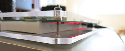
I’m going out of order here because I came up with this design as I laid out the board, but it fits better as its own section. As I mentioned, I had originally built an acrylic enclosure in the campus shop, designing the entire apparatus to hang from the back plate using either double stick tape or standoffs. This was a haphazard arrangement, and designing my own board opened up an opportunity to simplify things.
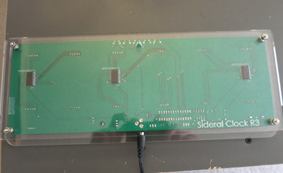
I discovered Ponoko (ponoko.com), which will laser cut from an SVG and mail directly to your door. Given that I had spent most of a day in the shop simply waiting for an opportunity to use the laser cutter (behind a long line of students who had never used it before and had come essentially unprepared to cut anything), I decided to give them a try. Despite the fact that they are listed as a New Zealand company, it turns out that their Acrylic shipped from a shop east of the San Francisco Bay, meaning that I would get my parts 24 hours after they shipped, even with the cheapest
shipping rates. Combine that with the $50 annual fee to use the campus shop and the long delay, I decided to give them a try. I got a discounted rate and my first piece ended up being on the order of $20, which was stunning. I ended up cutting two pieces of acrylic and using #4 screws to create a PCB sandwich, with a hanging hole in the back of the clock.
Unfortunately, there was a downside to clear
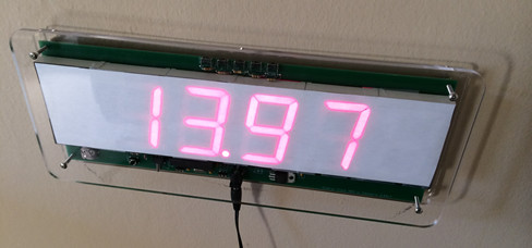
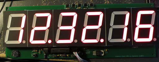
acrylic. Unlike the first LEDs, the new LEDs from Jameco have a black background (this is visible in the picture of the assembled board, to the right). This means that even the unlit LED segments have a fairly high contrast with their background. That lack of contrast makes the clock extremely difficult to read despite the display being absolutely huge. The first obvious solution was to use some thin paper as a diffuser, which works reasonably well, but it’s still not particularly pretty.

I decided to place a second order from Ponoko, of the same design, but in smoked gray acrylic. This design, diffuser omitted, came back absolutely beautiful and represents a nearly final design. The one last tiny change came from the realization that I could fit three clock enclosures on two sheets of acrylic if I shrank the height of the face by 0.1”.
The final BOM in quantity one is a little over $100, mostly due to the PCB, LEDs, and Acrylic, although I suspect in large quantities, it would be reduced to less than half that.
All in all, I’m really happy with how the entire clock came out and who knows, maybe at some point I’ll make a kit out of it or something, but for now, I intend to pass them out to friends and family as the occasional unique gift.
