Introduction
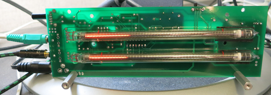
The IN-13 VU Meter is a ‘Nixie’ neon bargraph tube based VU-Meter. It takes stereo analog audio as an input (via a 3.5mm passthrough) and displays the audio amplitude on the tubes. It is not a true VU-meter, as it is not calibrated, but it does do proper log conversion to give a realistic representation of ‘perceived’ loudness.

Figure 1: Final VU-Meter without enclosure.
Background
Several years ago, I discovered and subsequently became fascinated with Nixie tubes, whose warm neon glow stands in rather stark contrast to the sterile feel of modern LED displays. A few years later, I was speaking to my academic advisor about such things, and he introduced me to the IN-13 bar-graph tube. This three terminal tube works on the same principles as a Nixie, but instead of individual discrete segments, it has a continuously variable single column of neon light. His suggestion was an all-analog VU-Meter. I set to the task, and breadboarded a VU-Meter circuit with the log-converter using a diode in the feedback loop of an op-amp and a few buffers. It worked, but it wasn’t as clean or adjustable as I would have liked, so while I had laid out a PCB I never went to the trouble of actually ordering it. The design did have a homebrewed 555 based high voltage power supply (HVPS) though, which was a fun build.
I shelved the project and didn’t touch it for years, although I did occasionally ruminate on the subject. When I finally came back to the topic last month, I had settled on a design that used an 8-pin microcontroller (MCU) in lieu of an op-amp based log converter. This had several advantages:
- I could adjust the gain and offset of the log conversion without changing any hardware.
- I could add simple moving averages or other low complexity signal processing algorithms if I so desired.
- I could use the GPIO of the MCU to shut down the HVPS (conserving the tubes and energy) when no sound was detected for a few seconds.
I also opted to use a Taylor Edge HVPS as they had come down in price to under $14 and supplied more current than the cruder and larger 555-based circuit that I had built could offer. Armed with these design decisions I set off to build my VU-Meter.
Design Process
With a microcontroller system in mind, the key elements to build an IN-13 driver – the key being signal specifications for all stages were in place. To maximize the performance of my MCU, it needed a 0-5V input signal and a 0-5V output from the controller’s PWM pin. This allowed the use of a garden variety Arduino Uno for breadboard prototyping with a switch to an ATTiny85 (thanks to Sparkfun’s convenient programmer) for the final system.
Pre-Amplifier
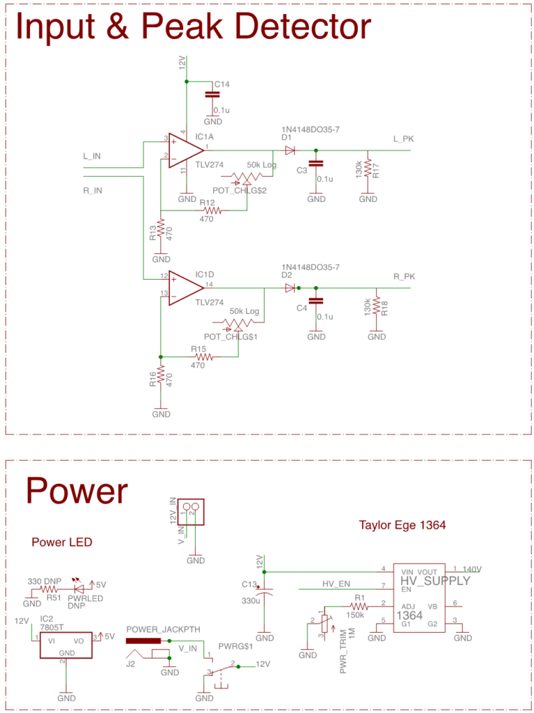
The first stage calls for a pre-amplifier to drive a peak detector circuit before the MCU. By putting the peak detector before the MCU, the bandwidth that the MCU needs is lowered from ~20kHz to the desired time constant of the output bar graph (<10Hz). Pre-amplifying the signal also guarantees that it is substantially larger than the 0.6V drop of the peak detector diode. This means that the system only requires a simple diode rectifier as opposed to a more complex precision rectifier. Figure 2 shows the input pre-amplifier and peak detector.

Figure 2: Power supply, input amplifier, and peak detector.

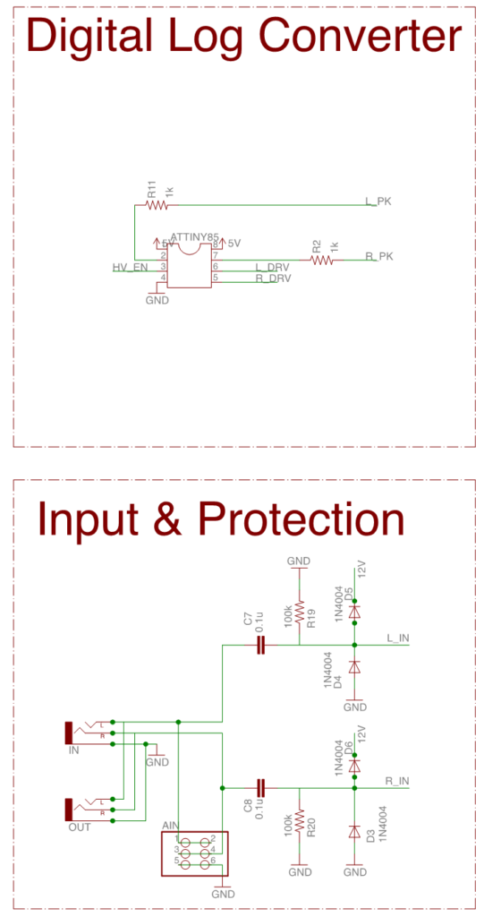
Figure 3: Input protection circuitry and ATTINY85 microcontroller

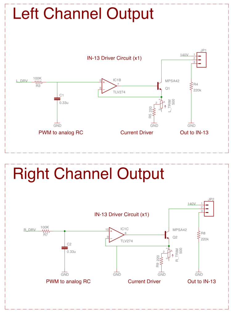
Figure 4: Output drivers.
Microcontroller Signal Processor
This conditioned signal feeds into the ADC of the MCU, where the MCU count is converted to a floating point 0-5V range. That voltage is then passed through the equation:
Vout = 6.2log10(Vin+1)
This provides a 0-5V log converted output. That output is in turn converted to an 8-bit integer and used to generate a PWM signal on a GPIO pin of the MCU. Figure 3 shows the MCU circuitry.
Tube Drive
The next stage is a low pass filter to convert the PWM to a constant voltage to drive the tubes.
The final stage of the system is a simple op-amp wrapped around a high voltage tolerant NPN transistor (MPSA42 or 44 do nicely). Figure 4 shows the PWM low pass and tube driver stages.
Current drawn from the middle pin of the tube controls the IN-13’s bar graph length. By setting the emitter resistor of the MPSA42, one can set the current pushed by the transistor. Placing that node inside the feedback loop of an op-amp goes one step further and removes the diode drop of the Vbe junction of the transistor.
One surprising thing found with these tubes is that the specified striking (ignition) voltage is 140V – that is the voltage you need to apply to get the tubes to illuminate at all, but the high side voltage had to be raised to 146-150 volts to get the tubes to reliably strike on power up. Additionally, the datasheets for the IN-13 all specify a full scale control current on the order of 5mA, but I found that I had to drive them with 11-15mA to get them to reach full scale. There may a design error here, but it seems that age may have something to do with their behavior as well.
PCB Design
After finishing the breadboard prototype the board was laid out in eagle added a few simple safety features were added. Firstly, there is a high pass filter (AC coupling) with a pole around 10Hz to the input, before the pre-amplifier (Figure 3). This guarantees that any damaged parts cannot cause stray voltages and damage source device. Additionally, AC coupling guarantees that the input signal was centered on 0V, protecting the VU-Meter and preventing DC bias from causing clipping. The op-amp itself is used to clip the negative half wave and rectify the input signal. Again, this is for simplicity and increased dynamic range. A more conservative design would bias the input signal to half scale before pre-amplification.
1n4001 protection diodes were added past the AC coupling to guarantee that large input voltages would not damage the quad op-amp used for all my signal stages (Figure 3 shows this protective circuitry as well as the high-pass).
The design choice of a ground-centered input on a single supply system required that I use a rail-to-rail opamp. The schematic lists the TLV274, which I did not have on hand or test, but was conveniently in my eagle library. I grabbed the amplifier I had handy, an LMC660, which is also a rail-to-rail component.
The MCU got some ADC input protection resistors as well. In the event of an overvoltage, the ADC has protection diodes tied to the power rails (much like the input stage of the system), adding a resistor in front of the ADC doesn’t change the input impedance of the ADC much but protects these diodes from overcurrent (also shown in Figure 3).
Finally, potentiometers allow for adjustment of control currents and the HVPS (Figure 2), as the PCB can’t have resistors casually swapped out to tune the tubes the way the breadboard prototype could.
Manufacturing, Assembly, and Enclosure
After a quick search for the cheapest board manufacturer (pcbshopper), ten boards cost $40 shipped from Accutrace (PCB4U) and the results were excellent. Compared to an advanced circuits prototype run (previously the benchmark for US made low cost boards), the Accutrace boards have a shinier solder mask and appreciably sharper silkscreen – one can clearly make out the smallest reference notes on the board, unlike the smaller, more expensive batch from Advanced Circuits.
Assembly
The only caveat with the boards as they came back was a footprint mistake, which was due to user error. The board had a modified Sparkfun footprint for the Panasonic dual gang potentiometer used to control gain for the preamp (Figure 2). Fortunately, after judicious use of a Swiss Army knife, the design was salvaged and the PCB layout was modified for future runs.
Calibration
Calibration was fairly painless. The MCU enabled another handy feature – the system tests the tubes at power up by linearly progressing from zero to full scale. For actual tube adjustment, it is simple to input a test tone, using a tool like online tone generator and sweep from zero to full scale, then use the sound card to pan the balance left to right.
Additionally, testing revealed that despite using a 12V supply for breadboard testing (it was handy), the design has plenty of headroom with a 9V supply, and works just fine.
Enclosure
Using Inkscape for design and an Epilog laser cutter for fabrication, an enclosure was built. It consists of two sheets of smoked acrylic; these create a “sandwich” with the board in the middle using standoffs. The smoked acrylic transmits the orange glow of the tubes nicely, while masking the circuitry from a distance. The result is a floating vu-meter effect (Figure 5). The back panel of the enclosure also has picture hooks cut into it to allow the meter to be mounted either vertically or horizontally on a wall.

Figure 5: Board in acrylic enclosure.
Conclusion
The final project works well and looks absolutely gorgeous sitting on top of my home stereo. It works great as a standalone device but I fully intend to include a few of these into larger projects as integrated VU-Meters.
