As promised, here is a verified (I have used this and successfully assembled the boards) footprint / part for the PCM5102A I2S sound cards that can be found on amazon.
Here it is: PCM5102A.lbr
Electronics, Hacking, Stupid Ideas
As promised, here is a verified (I have used this and successfully assembled the boards) footprint / part for the PCM5102A I2S sound cards that can be found on amazon.
Here it is: PCM5102A.lbr
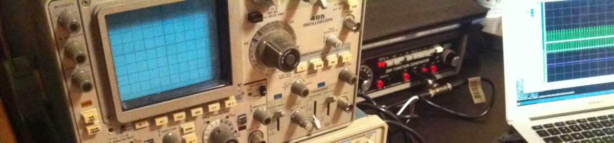
I feel like almost everyone who has had to deal with anything outside the most mundane audio setup on Linux machines has experienced the pain I’m about to describe. On Mac and Windows machines, audio seems to ‘just work’ (TM) (R) (C) — and on linux desktops like Ubuntu it seems to be fine too.
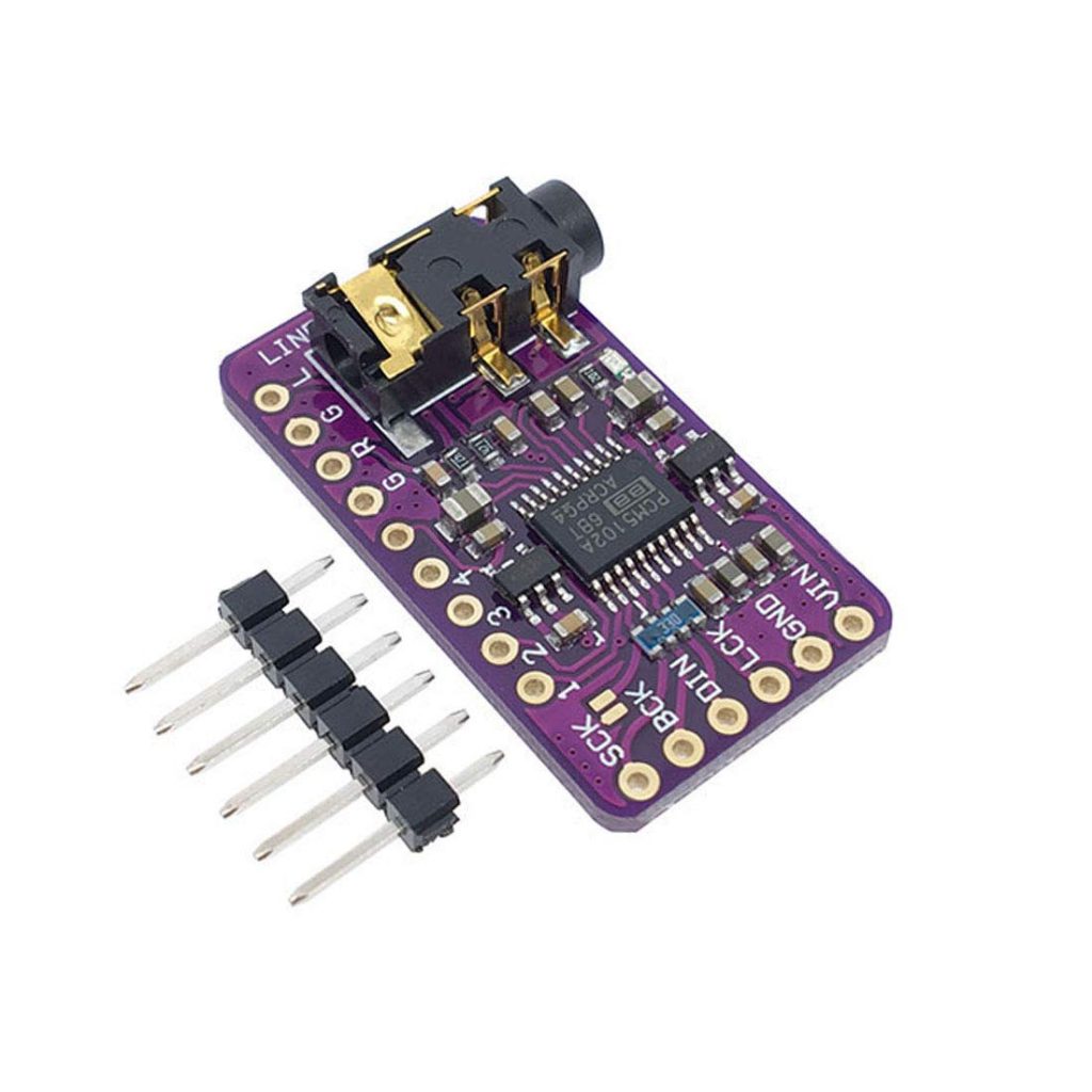
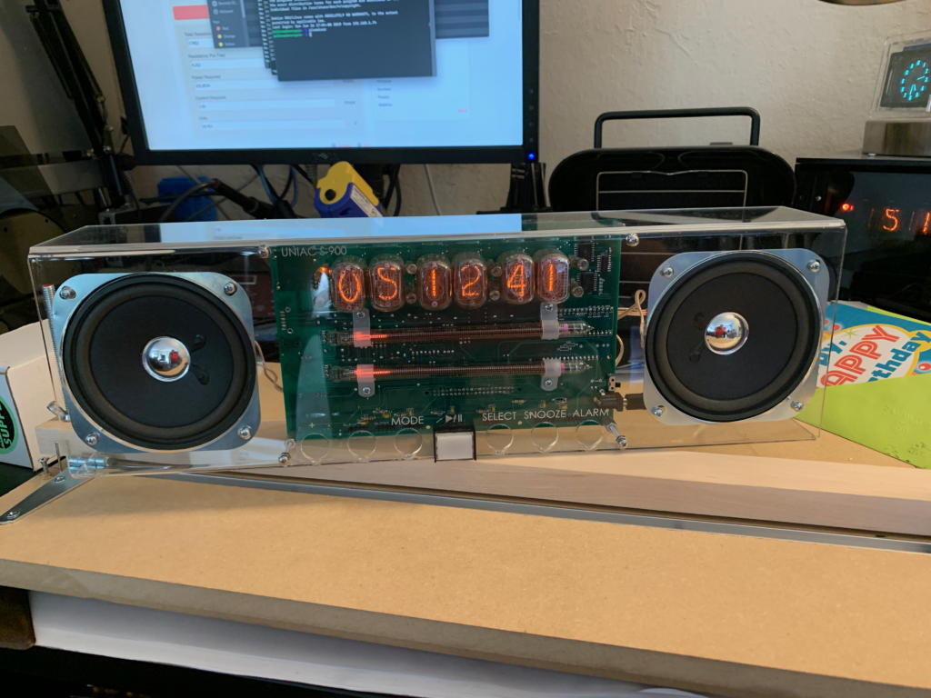
For my UNIAC project however, I went a little off the rails (dun-dun-dun). UNIAC 2.0 uses a Raspberry PI Zero W, which doesn’t come with any onboard analog audio output, forcing me to use a third party sound card. Since the project had a nice backplane motherboard, I wanted a module I could just plop down on the board as if it were a component. Ultimately, I settled on a PCM5102A module like this one, which took audio as I2S samples and cost all of $8. For the final, working version of this, I used Raspbian Buster (July 2019).
As an aside, I created an EAGLE Footprint for the module, so you can incorporate one into your own projects if so desired.
To get it all working, we need the OS to do four things:
These no-name PCM5102A modules are sketchy at best, and come with no meaningful support and no manual. Fortunately, they use the same IC as the Hifiberry DAC+ project. After getting this thing going I feel somewhat bad for not buying their board, but the form factor is just not what I need.
In theory you can follow the Hifiberry DAC+ setup instructions to get basic output going – but don’t use them if you want software volume control. For me following those instructions resulted in a weird situation where the software volume control didn’t actually stick after reboot, so I recommend staying away.
What did work for me, was a modified version of these instructions. To get basic volume control working, I used the first few steps of those instructions. I’ll duplicate them here in case the site goes down.
First we need to disable the onboard sound by editing alsa-blacklist.conf:
sudo nano /etc/modprobe.d/alsa-blacklist.confAdd:
blacklist snd_bcm2835Save and exit (^X, Y, enter).
Now, to set the IO, edit config.txt:
sudo nano /boot/config.txtAdd:
dtoverlay=hifiberry-dacRemove or comment (#) the line:
dtparam=audio=onLeave the line:
dtparam=i2s=oncommented out.
Save and exit (^X, Y, enter).
Next add some alsa (sound) configuration:
sudo nano /etc/asound.confPaste the text below:
pcm.!default {
  type hw
  card 0
}
ctl.!default {
  type hw
  card 0
}
Save and exit (^X, Y, enter).
It is no harm to do a reboot. So:
sudo rebootTest if everything is OK:
aplay -lThis should return:
**** List of PLAYBACK Hardware Devices **** card 0: sndrpihifiberry [snd_rpi_hifiberry_dac], device 0: HifiBerry DAC HiFi pcm5102a-hifi-0 [] Subdevices: 1/1 Subdevice #0: subdevice #0If you have an amplifier you can connect via a phono lead you can now test it via: speaker-test -D -c -twav So:
speaker-test -D default -c 2 -twavThis is a continuous test saying ‘front left’ and ‘front right’ alternately from the appropriate speakers. Enter ^C to stop.
This is an optional step that adds a software volume control into the sound processing sequence.
sudo nano /etc/asound.confadd the following:
pcm.sftvol {
   type softvol
   slave.pcm "plughw:0"
   control {
     name "PCM"
     card 0
   }
Enter or change the pcm.!default section to:
pcm.!default {
   type plug
   slave.pcm "sftvol"
 }
Save and exit (^X, Y, enter).
Now we can test it, as before:
speaker-test -D default -c 2 -twavThis should give alternating “front right” and “front left” from the respective speakers.
Here’s where we go off the rails. We need to add a software mixer to this cozy little ALSA setup. Fortunately, DMIX is a thing. There are a few dmix examples out there. What we need to do, however, is connect dmix to softvol to a PCM sound device. This I could not find documented clearly anywhere on the internet, so here we are.
pcm.!default {
  type plug
  slave.pcm "softvol"
}

pcm.softvol {
  type softvol
  slave {
    pcm "dmix" #redirect the output to dmix
  }
  control {
    name "PCM" #override PCM slider to set softvol lvl globally
    card 0
  }
}To get MOPIDY to work (my ultimate goal here), I had to do two things:
In mopidy.conf, I had to change the audio section to this:
#mixer = software
mixer = alsamixer
output = alsasink device=plug:softvol
#mixer_volume =
#output = autoaudiosink
#buffer_time =
And then I added an alsamixer config as follows:
[alsamixer]
card = 0
control = PCM
min_volume = 0
max_volume = 100
volume_scale = cubic
Finally after weeks of pain, I’ve arrived at a configuration that works!
A few months ago, I was thinking about the best way to build enclosures for my projects. My go-to has been the ‘acrylic sandwich’ method, where I laser cut a handful of pieces of acrylic and bolt them to my PCB with standoffs.
This looks reasonably good. More professional than hand built project enclosures, and less cookie-cutter than using a standard project box. But it has its drawbacks and limitations. You can cut slots in the front and back of your project and then use the tension in the standoffs to hold side panels in place, but these slots have to have a fair bit of slop in them as the thickness of acrylic sheets varies fairly significantly from manufacturer to manufacturer and even seems to vary lot to lot from cheap vendors.
To deal with this, I decided to build an acrylic bender. Basically, acrylic has a very low melting point, so a beefy benchtop power supply can heat up nichrome wire, enough to bend it. Nichrome wire is the same stuff that cooks your toast in the morning, and it can be had rather cheaply off of Amazon. To build an acrylic bender, basically all you need to add to the two aforementioned components is some bits and bobs from home depot. In my case, I got one 24″ x 24″ sheet which I got cut three times to form a base, a working area and a hinge area. You add a small amount of U-channel under the hinges, and voilá, you have a bender.
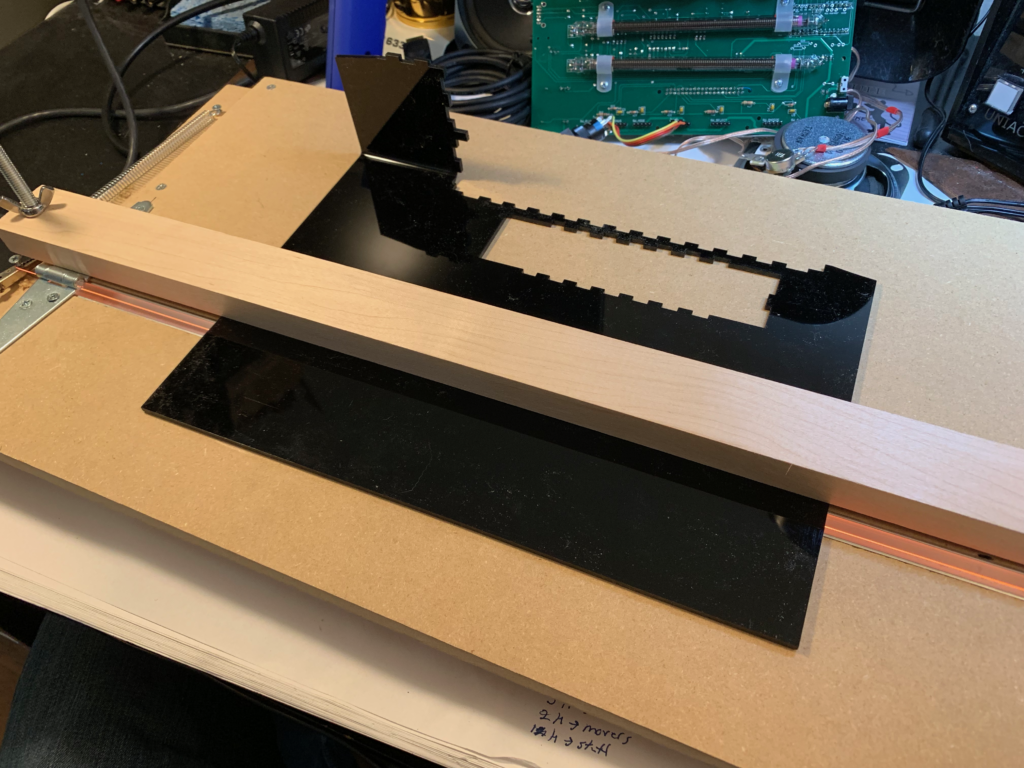
With one afternoon of building, I had myself a jig that was trivial to use and cost less than $50 total, way less than what you’d pay for a professionally made device online.
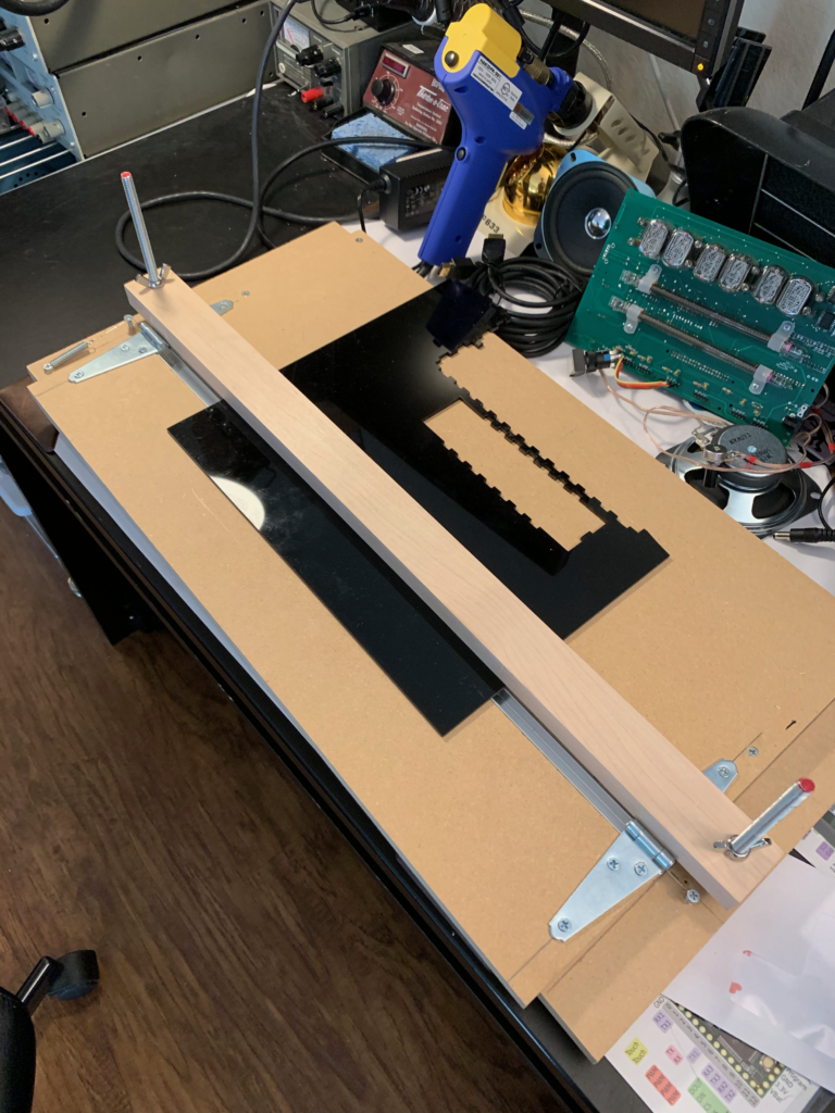
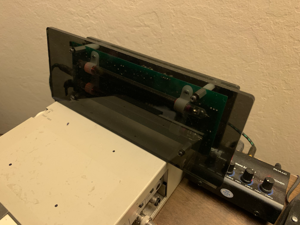
With that I set about making the enclosure I had in mind:
The angles are pretty easy to make, and I don’t have a protractor to get exact angles (definitely a future improvement)! With my 35V 5A benchtop supply, it only takes about five minutes to get the acrylic hot enough to bend easily, and then you have to hold it in position for three or so additional minutes while it cools off.
One note, which you can see in the above picture, is the danger of having holes or edges in your acrylic close to the bend line. The hole edges themselves softened and deformed with the bend. In a later revision of the enclousure, I backed off the holes by ~1/2″ and saw no deformation, so it’s not a major drawback.
Now, with two bent pieces of acrylic, I can make a neat clamshell enclosure that is sturdy and looks professional. Definitely worth the investment.
For a while, I’ve been thinking about noise cancelling microphones. I realized the other day that in order to ever hope to build one, I needed to model it first. What I ended up doing was building a model in matlab (of course), which includes the following simple classes:

Then, to get waveforms, you can take the output audio from multiple microphones (which is effectively time aligned) and do math with it.
Then, by sweeping the wave sources through space, we can plot the pickup patterns of different wave forms.
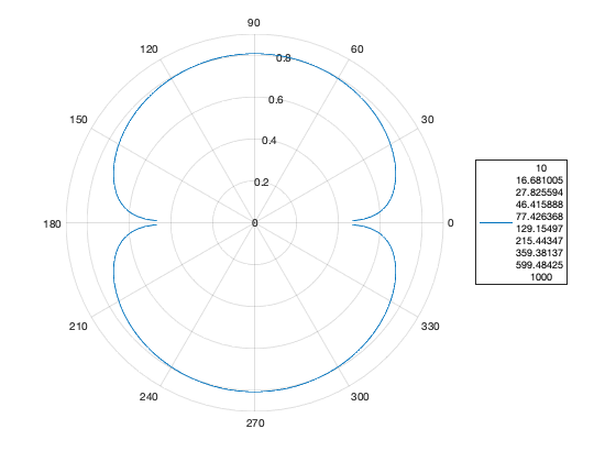
By sweeping the frequency of the waveform over successive sweeps, we can see that impact as well.
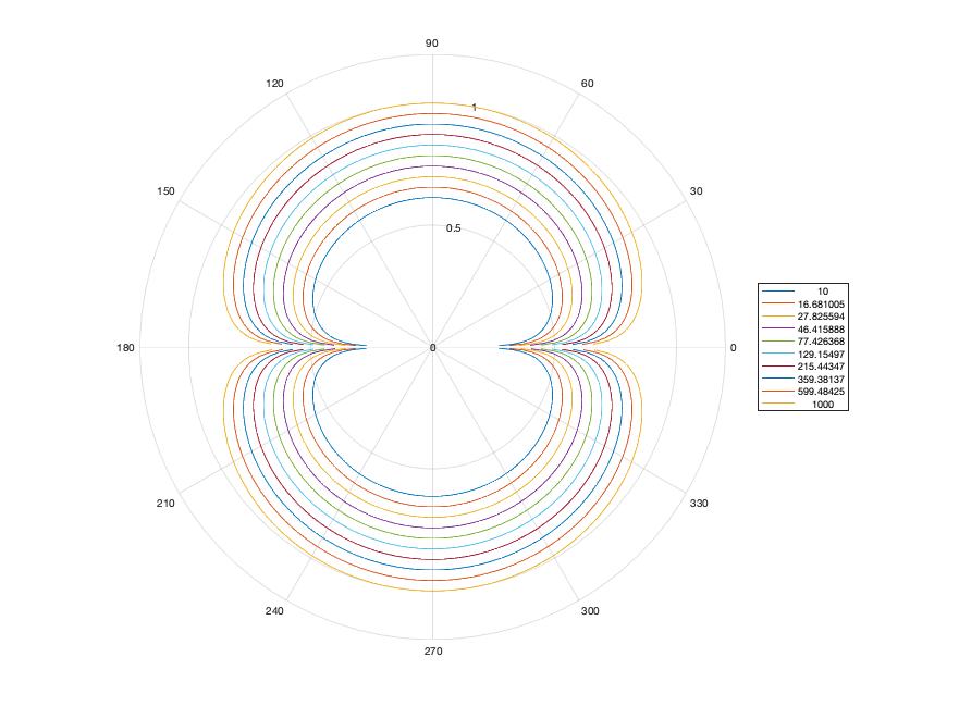
Fun. More to come?
Get the code here: https://github.com/wespo/DirectionalMicrophone
Just a quick one — I haven’t posted here in forever, and I have lots of things which I really should document. This is one that I finished a few weeks ago but was super quick. Basically, it’s just an artsy-fartsy lamp. I built it using this light bulb, from Amazon, some styrofoam to create the mid-lamp platform. Fake grass from Michael’s Crafts for the grass.
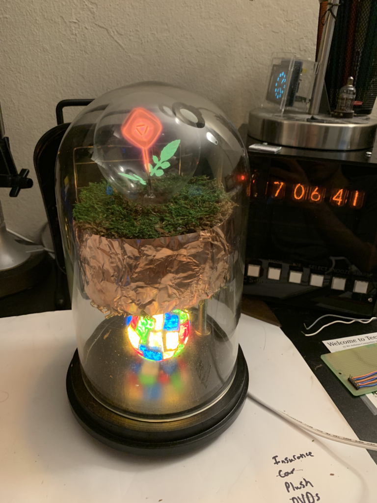
The original bulb for the bottom that inspired the design was a 25W incandescent ‘stained glass‘ bulb, but the heat from that bulb trapped inside the glass cloche would quickly begin to bake the oils out of the fake grass. This was a pretty severe fire hazard, so I took an LED bulb and hand painted it using sharpie paint pens. A little gauche, but it adds a certain wabi-sabi value to the art that matches the hand crumpled copper tape which rings the ‘grass’ platform. All in all, I’m pretty pleased with how it came out.
Okay, so the one piece of hardware that hasn’t been much discussed in this chain is the processor. I chose an atmega 328p for a couple of reasons:
With the decision made, I set out to use the atmega on a breadboard, as laid out here. Since I’m lazy and didn’t want to lay down a crystal or capacitors, and I need next to no performance, I opted to use the internal 8MHz oscillator.
Unlike the tutorial, I simply socketed the atmega into an unused UNO and plugged it in to my Sparkfun AVR Programmer. After burning the bootloader and program, I dropped it in to my breadboard and went with it. This is the first time I’ve used the 8MHz oscillator and it did exactly what it said on the tin.
To drive the VFD, I initially tried to use a pre-made seven segment library, SevenSeg. Despite the fact that it looks like it should work, I couldn’t get it to turn on the display. Given that I wasn’t using any of the complex features, like multiplexing, I decided to save time bit-bang the pins myself.
The resulting functions were as follows:
#define SEG_A 0
#define SEG_B 1
#define SEG_C 2
#define SEG_D 3
#define SEG_E 4
#define SEG_F 5
#define SEG_G 6
#define SEG_DP 7
#define PWR 12
int pinDefinitions[8] = {SEG_A, SEG_B, SEG_C, SEG_D, SEG_E, SEG_F, SEG_G, SEG_DP}; //array of pin segments
byte charArray[10] = { //array of segments to light up for each digit 0-9
  0b11111100,
  0b01100000,
  0b11011010,
  0b11110010,
  0b01100110,
  0b10110110,
  0b10111110,
  0b11100000,
  0b11111110,
  0b11100110
};
void initSegPins(int* pins) //initialize the pins
{
  for(int i = 0; i < 8; i++)
  {
    pinMode(pins[i], OUTPUT);
  }
}

void setDisplay(int num, int* pins) //draw a digit 0-9 on pins
{
  num = num % 10;
  byte segments = 0x00;
  writeArb(charArray[num], pins);

}

void writeArb(byte segments, int* pins) //draw an arbitrary byte on pins
{
  for(int i = 0; i < 8; i++)
  {
    digitalWrite(pins[i], (segments>>(7-i))&0x01);
  }
}
void setDisplay(char c, int* pins) //draw a character on the pins
{
  if((c > 0x2F) && (c < 0x3A)) //digit 0-9
  {
    setDisplay((int) c - 0x30, pins);
  }
  else
  {
    switch(c) {
      case 'f':
      case 'F':
        writeArb(0b10001110, pins);
        break;
      case 'c':
        writeArb(0b00011010, pins);
        break;
      case 'C':
        writeArb(0b10011100, pins);
        break;
      case 'd':
        writeArb(0b01111010, pins);
        break;
      case 'D':
        writeArb(0b11000110, pins);
        break;
      case 'h':
        writeArb(0b00101110, pins);
        break;
      case 'H':
        writeArb(0b01101110, pins);
        break;
      case 'b':
        writeArb(0b00000000, pins);
        break;
    };
  }
}
void printNum(float num, int* pins, int delayLen = 500) //print a number up to 999, rounded to nearest int
{
  num = round(num);
  if(num > 100)
  {
    setDisplay(int(floor(num/100))%1000, pins);
    delay(delayLen);
  }
  if(num > 10)
  {
    setDisplay(int(floor(num/10))%100, pins);
    delay(delayLen);
  }
  setDisplay(int(floor(num))%10, pins);
  delay(delayLen);
}
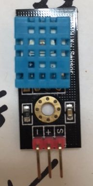
The final piece of the puzzle was the DHT11 temperature sensor. Since I didn’t have one on hand, this represented the only cash expenditure for this project — $10 at Fry’s. I grabbed on OSEPP DHT11 breakout board, since it was what they had. It had the advantage of getting humidity as well, so I made the program report that in addition to temperature. Fortunately, Adafruit also sells DHT11s, so I was able to use their library, although I did need to also install their general sensor library. These libraries are the real perk of using the Arduino environment, admittedly.
The final code for the entire program is here:
#include "DHT.h"

#define DHTPIN 13     // what digital pin we're connected to

// Uncomment whatever type you're using!
#define DHTTYPE DHT11   // DHT 11

// Initialize DHT sensor.
// Note that older versions of this library took an optional third parameter to
// tweak the timings for faster processors.  This parameter is no longer needed
// as the current DHT reading algorithm adjusts itself to work on faster procs.
DHT dht(DHTPIN, DHTTYPE);


#define SEG_A 0
#define SEG_B 1
#define SEG_C 2
#define SEG_D 3
#define SEG_E 4
#define SEG_F 5
#define SEG_G 6
#define SEG_DP 7
#define PWR 12
int pinDefinitions[8] = {SEG_A, SEG_B, SEG_C, SEG_D, SEG_E, SEG_F, SEG_G, SEG_DP}; //array of pin segments
byte charArray[10] = { //array of segments to light up for each digit 0-9
  0b11111100,
  0b01100000,
  0b11011010,
  0b11110010,
  0b01100110,
  0b10110110,
  0b10111110,
  0b11100000,
  0b11111110,
  0b11100110
};
void initSegPins(int* pins) //initialize the pins
{
  for(int i = 0; i < 8; i++)
  {
    pinMode(pins[i], OUTPUT);
  }
}

void setDisplay(int num, int* pins) //draw a digit 0-9 on pins
{
  num = num % 10;
  byte segments = 0x00;
  writeArb(charArray[num], pins);

}

void writeArb(byte segments, int* pins) //draw an arbitrary byte on pins
{
  for(int i = 0; i < 8; i++)
  {
    digitalWrite(pins[i], (segments>>(7-i))&0x01);
  }
}
void setDisplay(char c, int* pins) //draw a character on the pins
{
  if((c > 0x2F) && (c < 0x3A)) //digit 0-9
  {
    setDisplay((int) c - 0x30, pins);
  }
  else
  {
    switch(c) {
      case 'f':
      case 'F':
        writeArb(0b10001110, pins);
        break;
      case 'c':
        writeArb(0b00011010, pins);
        break;
      case 'C':
        writeArb(0b10011100, pins);
        break;
      case 'd':
        writeArb(0b01111010, pins);
        break;
      case 'D':
        writeArb(0b11000110, pins);
        break;
      case 'h':
        writeArb(0b00101110, pins);
        break;
      case 'H':
        writeArb(0b01101110, pins);
        break;
      case 'b':
        writeArb(0b00000000, pins);
        break;
    };
  }
}
void printNum(float num, int* pins, int delayLen = 500) //print a number up to 999, rounded to nearest int
{
  num = round(num);
  if(num > 100)
  {
    setDisplay(int(floor(num/100))%1000, pins);
    delay(delayLen);
  }
  if(num > 10)
  {
    setDisplay(int(floor(num/10))%100, pins);
    delay(delayLen);
  }
  setDisplay(int(floor(num))%10, pins);
  delay(delayLen);
}
void setup() {
  // put your setup code here, to run once:
  initSegPins(pinDefinitions);
  digitalWrite(PWR, HIGH);
  pinMode(PWR, OUTPUT);
  dht.begin();
  delay(500);

// Read temperature as Fahrenheit (isFahrenheit = true)
  float f = dht.readTemperature(true);
  printNum(f, pinDefinitions);
  //print degree symbol and F
  setDisplay('D', pinDefinitions);
  delay(500);
  setDisplay('f', pinDefinitions);
  delay(500);

  //blank display
  setDisplay('b', pinDefinitions);
  delay(500);

  float h = dht.readHumidity(); //humidity
  printNum(h, pinDefinitions);
  setDisplay('H', pinDefinitions);
  delay(500);

  //turn off system
  digitalWrite(PWR, LOW);

}


void loop() {

}
So, what does the final project look like? Like this!
What is it showing? The temperature (two digits), then the degrees symbol and F. This is followed by a pause, then it reports percent humidity and the letter H (for humidity).
That’s all folks! Hope you enjoyed the read. On to the next project.
Okay, so power problems solved, it was time to address the control issue.
The first problem was driving the filament. The filament is roughly 12Ω and it is recommended to drive at 1.5V and about 100mA. There is scant information online, and that which I have found suggests things like using several diode drops or a zener diode from a 5V supply to get 1.5V, a current limiting resistor, or the like.
Giving it some thought, I decided to take a different approach: current control. Taking a page from LED control, I used a classic constant current supply circuit, as shown below.
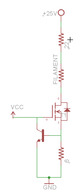
The 6Ω resistor sets the current of the driver, which is rougly I_load = 0.6V / R_Set where 0.6V is the turn on of the NPN control transistor. To turn on, the FET must have a Vgs < Vcc (5V in this case). Since the power dissipated by the FET is P = I_load (0.1A) * Vds, and without the 22Ω resistor, it would be: Vds = Vcc-0.6-V_load = 5 – 0.6 – 1.2 = 3.2V
Thus, the FET would be dissipating 0.1 * 3.2 = 0.32W. To alleviate that, the 22Ω dropper resistor is placed in series with the load, resulting in Vds = Vcc – 0.6 – 2.2 – V_load = 5 – 0.6 – 2.2 – 1.2 = 1V meaning the FET will dissipate 0.1W and the 22Ω resistor will dissipate 0.22W.
Thus, we can be confident of the current that will be passing through our filament even if something goes haywire with the power supplies.
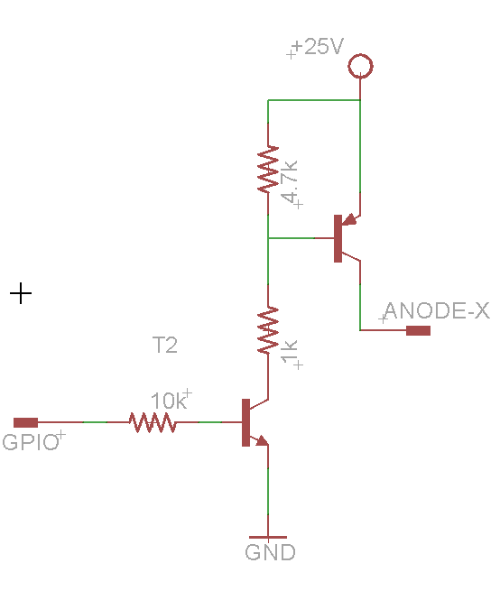
To control the actual segments of the VFD, we have to pull each anode to +25V. Obviously, our microcontroller cannot do this, and cannot handle exposure to 25V levels in any case. Fortunately, unlike Nixies, where the approximately 200V levels are far too high for “jellybean” transistors to handle, 25V is well within the 40V range of classis 2N2904/2N3906 NPN/PNP transistors. Therefore, we can use a standard high side switch circuit to control the anodes, driving each pin with the GPIO of our microcontroller.
The final part of the circuit is the temperature sensor. I used an off the shelf OSEPP DHT11 module that I found at Fry’s — it only takes Vcc (5V), GND, and a signal pin, and I used the standard Adafruit DHT11 library to communicate with it. More on that (and the software in general) in the next post.
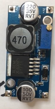
In our last adventure, we lit the IV-11 with benchtop power supplies. Nice to show that we know how it works. Now, it’s time to build a project around it. After some thought about what I would like to display with a single digit seven segment display, I chose a thermometer. Taking up a wall outlet doesn’t make much sense either, so it would have to be battery powered and fairly energy efficient. To drive the IV-11, I’d need a 25V supply as well. Fortunately, in my parts bin, I had a couple of tricks up my sleeve. First, I had a handy $2 boost supply from china. I also had a spare Murata 7805 replacement, which provides a drop in replacement for the classic LM7805 linear regulator, but at a higher efficiency (and without the strict need for the off board filter caps)!
The 5V rail would provide power for several things. Most obviously, it would supply power to the microprocessor (an Atmega 328P) and sensor (a DHT11 module from OSEPP, picked up at my local Fry’s — more on that in a later post). Additionally, the 5V rail would provide power for the filament — this would be more efficient than some sort of resistor divider down from 25V.
The final part of the power supply would be the soft power module. It’s a circuit I’ve used before, based off the Dave Jones soft power switch.
My modification omits the hardware “power off” functionality — the button latches the power supply on, and the microcontroller has the ability to switch the circuit off by pulling a GPIO pin low.
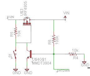
Using this power switch, the system can be turned on by a user pressing the power button, run its temperature measurement routine, and shut itself off, using absolutely no standby power.
I had originally hoped that I could use a couple of lithium coin cell batteries to power this, but I realized that I’d be taking a couple hundred milliamps at full draw. Clearly, this wasn’t in the cards for lithium batteries, which have high internal resistance. Nonetheless, a single 9V battery ended up being a reasonable compromise.
A couple of years ago (yes, years) I was given an IV-11 VFD tube. VFDs are a class of tube that is less popular among hobbyists than the more beloved orange Nixie tube — although they are often mistaken for them by newbies.
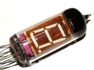
Having no idea just how to drive the tube, I dropped it into the bottom of my Nixie parts bin (ironic, admittedly). There it languished until about three weeks ago, when I decided I needed a weekend project and would like to try and build a circuit around it. Step one was to figure out if I could light the tube.
Fortunately, the ever handy Dieter’s Tube Archive had a translated datasheet. Important because the tubes are surplus from the Soviet Union, meaning that the original datasheet was in Russian!
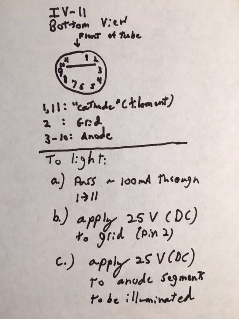
With a datasheet in hand, I knew the voltages and currents needed, so I was off to the races. Taking the pinout from the datasheet, shown below,
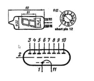
I switched on my two trusty benchtop power supplies (both are single output), set my voltage and current limits, and was all set to go… or so I thought.
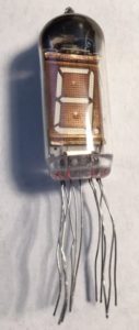
Here’s where reality and the datasheet collide. The datasheet says there is a “short pin 12”. In reality, there is no pin 12 at all, just a gap. Alright, that’s a warning sign, but not the end of the world. The gap however, means that the datasheet view of the bottom of the tube has the rotation at about 45 degrees. It also took me some time (and observation of the internal construction of the tube) to determine that this pinout was a bottom view of the tube, not the top. To save the rest of you the time I wasted making heads or tails of this, here’s my IV-11 pinout.
To finish my testing, I simply connected the appropriate anode segment to 25V to light it. I was going to include a picture here of the VFD lit this way. Thing is…I didn’t take a picture of it lit back then, and when writing this post, I managed to blow it up by swapping pins 1 & 2 with my alligator clips. On the plus side, the filament made a really bright lightbulb for a few hundred milliseconds. Oh well, they’re only $3/ea on eBay from the US. Way less if I’m willing to wait for shipping from Russia. At this point, I’m invested enough to buy a couple more.
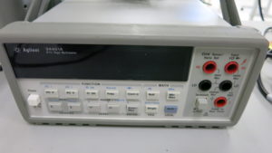
One problem with choosing closely matched resistors is that 0.1% of 1MΩ is 1kΩ. Most multimeters are rated in “digits”, e.g. “4 1/2 digits”. This means that they can display a range from 0 to 19999. This means that with a ~1MΩ resistor, you can measure ±50Ω steps. This is enough to measure resistor tolerance within 0.005%, but the more digits the better. Since I happened to have an HP 34401A 6 1/2 digit multimeter handy, I figured that overkill was the better part of valor.
Then, I set about sitting down and measuring the value of 30 resistors or so.
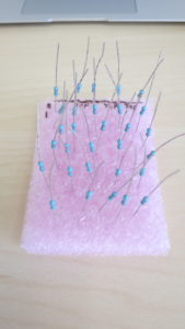
Once I had them all measured, I had to pick a set of closely matched resistors. Simply writing all the values down, it’s easy to pick a pair of closely matched resistors, but I needed two sets of eight closely matched resistors. The result was the following Matlab script, which picks the closest set of numbers from a group.
function [closestVals closestPos] = smallestSet(randomVals, number)

randomSize = size(randomVals);

if(randomSize(2) == 1)
    randomVals = randomVals.'
end

closestVals = randomVals(1:number);
closestPos = (1:number);
range(closestVals)
for value = randomVals
    if(value == -inf)
        continue;
    end
    nearVals = zeros(1,number);
    nearPos = zeros(1,number);
    distVals = abs(randomVals - value);
    for n = 1:number
        [minVal minPos] = min(distVals);
        nearVals(n) = randomVals(minPos);
        nearPos(n) = minPos;
        distVals(minPos) = inf;
    end

    if(range(nearVals) < range(closestVals))
        closestVals = nearVals;
        closestPos = nearPos;
    end
end
Using this script, I turned my random pile of 30 1% resistors into two sets of 8 resistors matched to better than 0.05%. While the value they are centered around is not exactly 970kΩ, the spread of values means that my CMRR does much better than a 1% priced pile of resistors should deliver, and it cost me a lot less than buying sixteen 0.05% matched resistors!